Turner/ Jenbach/ List & Cerlist Diesel Engines
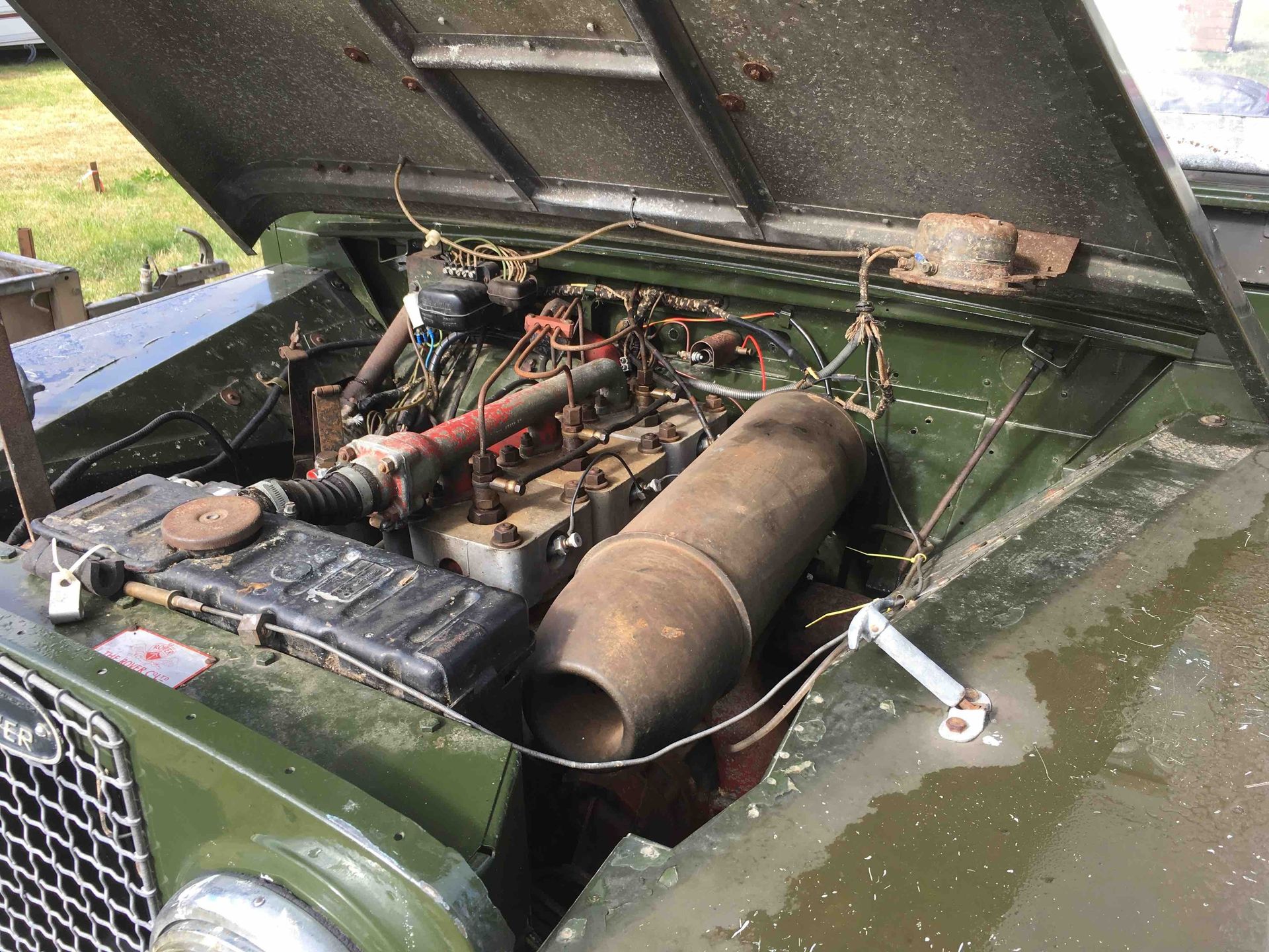
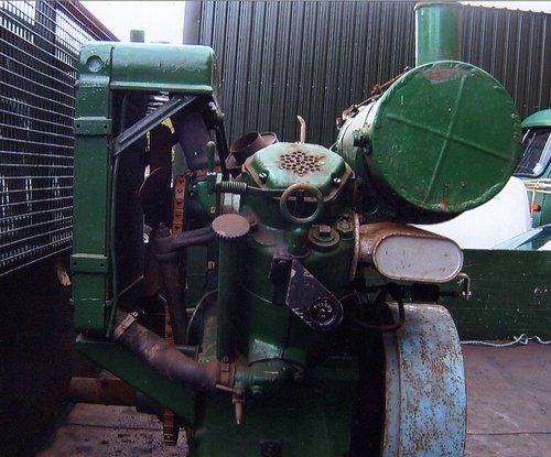
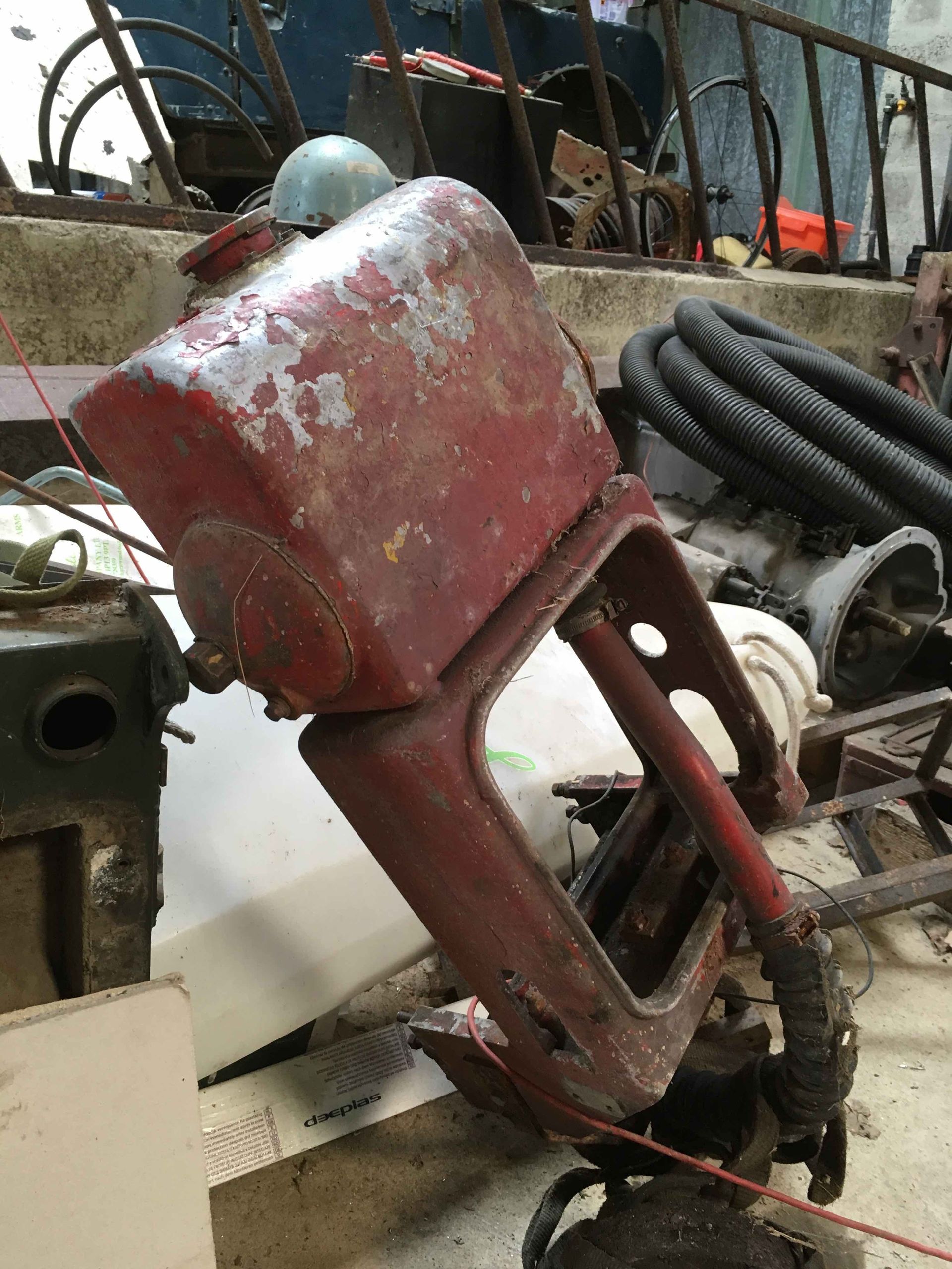
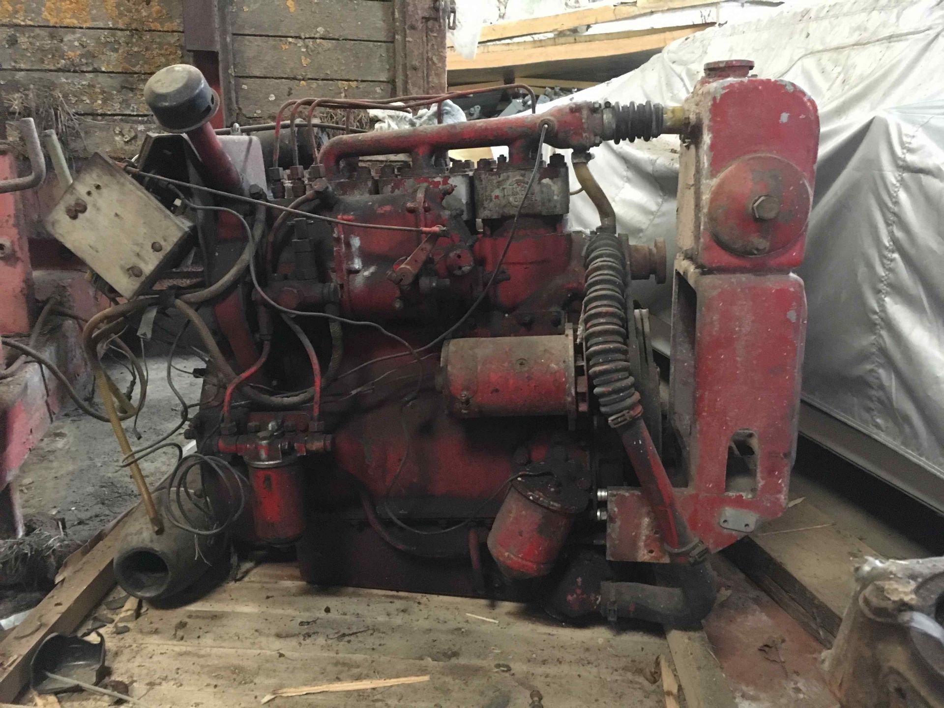
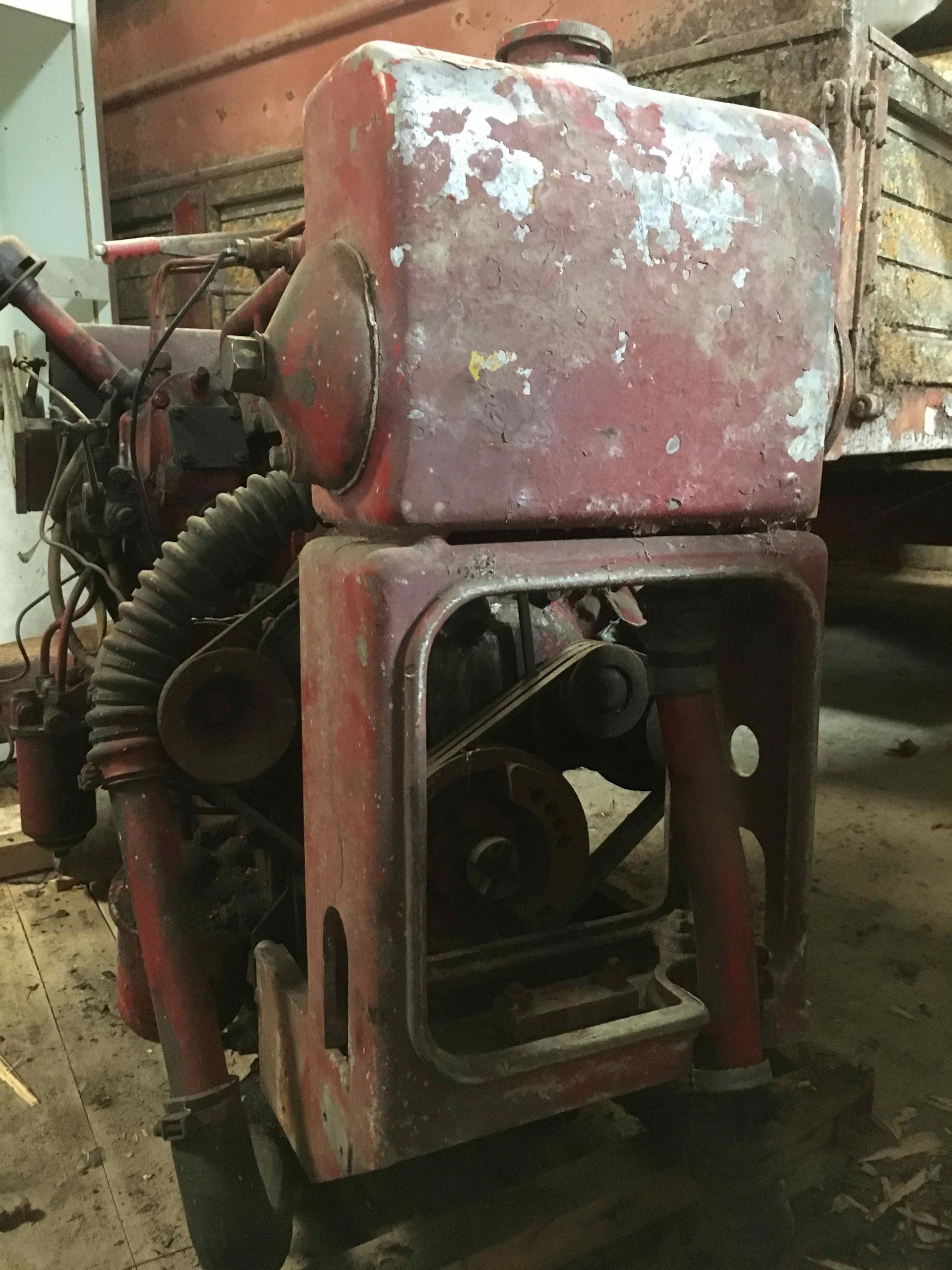
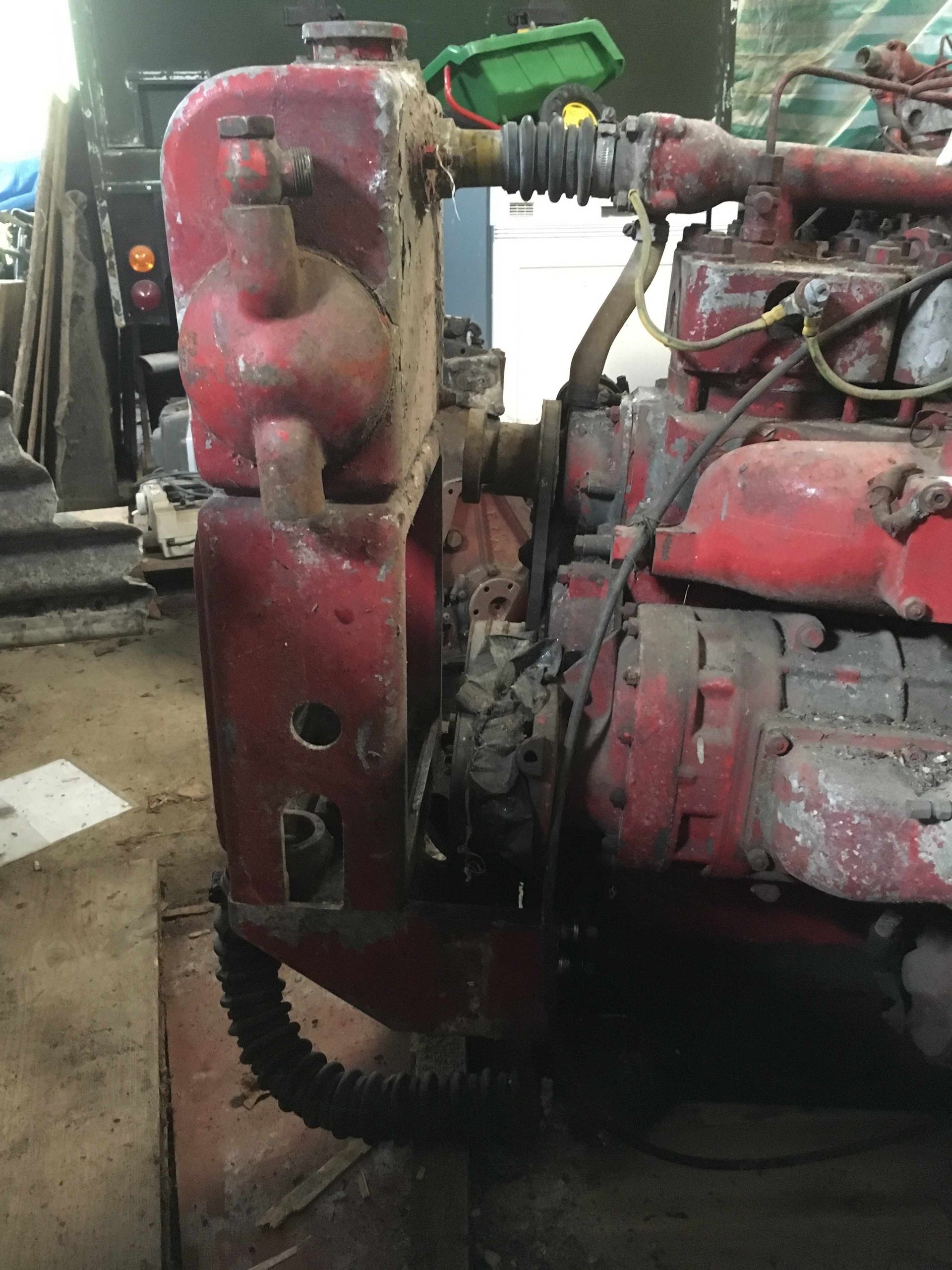
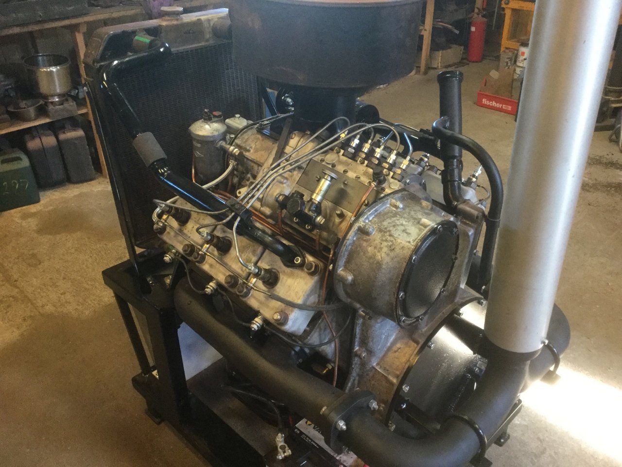
L60 Turner engine installed in my ex MoS 1957 88" Series One Land-Rover - unfortunately this vehicle was destroyed in the steading fire of 2019.
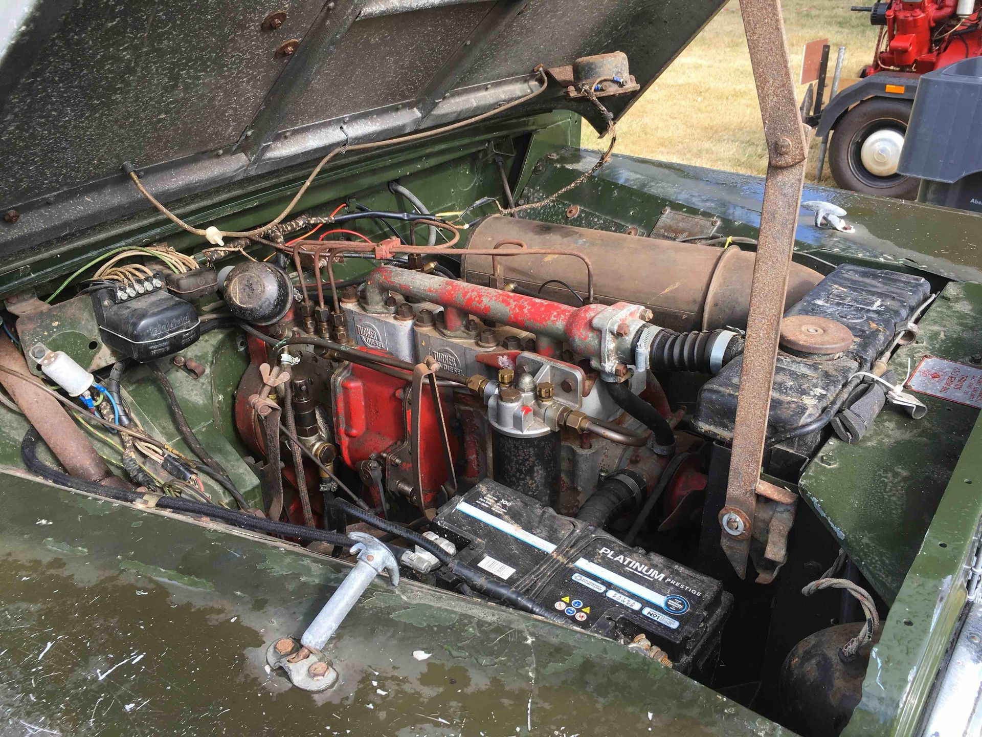
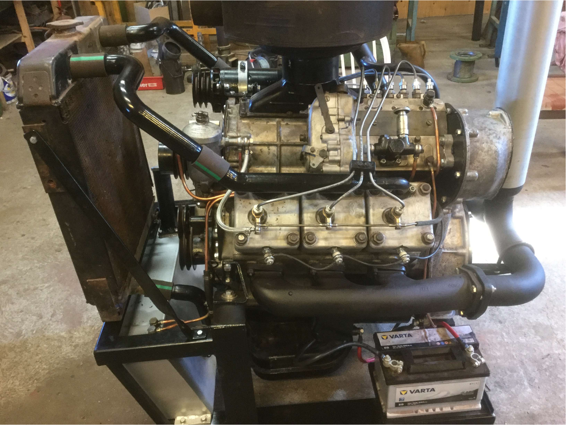
Engine installation viewed from the other side
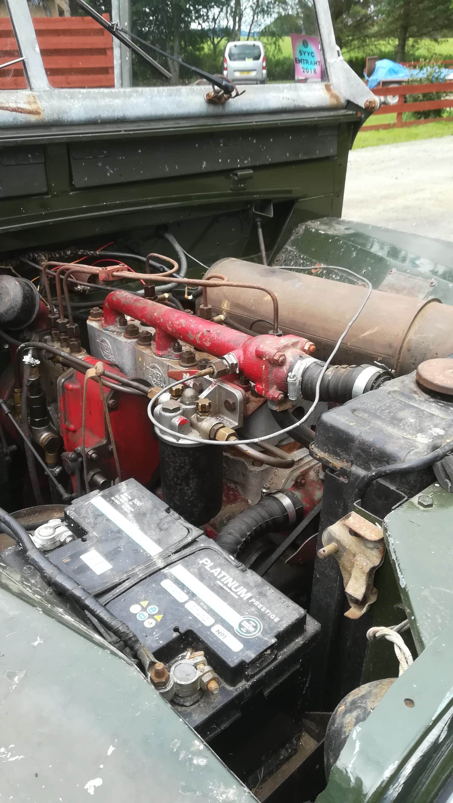
Water temperature bulb fitted but needing re-routing.

Dual gauge currently fitted, Series One aficionados will observe that this is a later gauge as it has the Land-Rover logo on it.
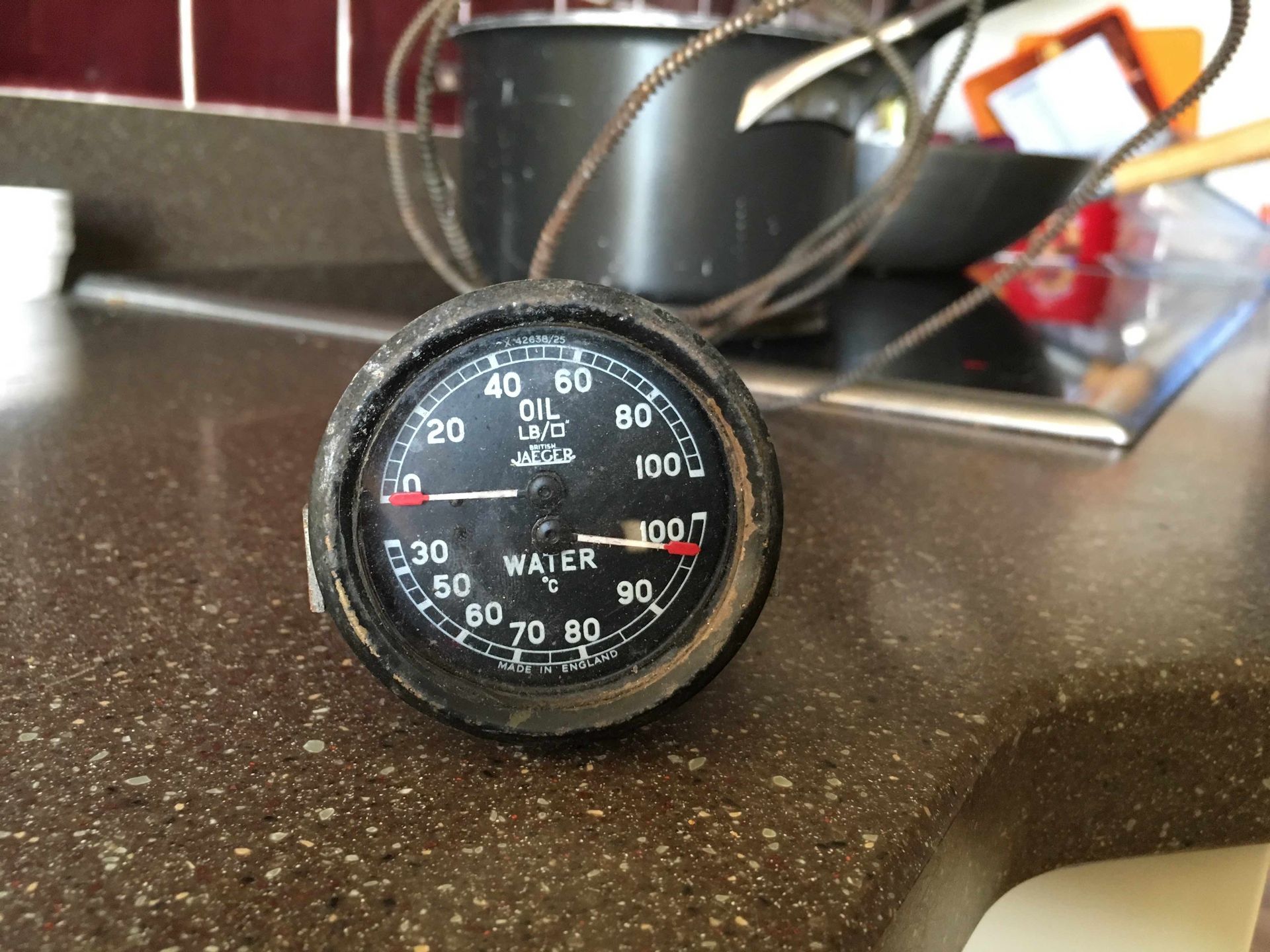
The gauge I intend replacing it with under test.
The pictures above show a genuine Land-Rover designated Turner L60 diesel engine fitted to my ex Civil Defence 88" Land-Rover (this link takes you to Graeme Aldous's SXF site). I will at some point post some pictures of the build (if I can find the photo's and get them scanned).
It was fortunate that I also had a Land-Rover designated Turner L40 engine as well because the initial attempt to fit the engine mated to a standard Land-Rover gearbox had the engine too far back and the bulkhead simply didn't fit.
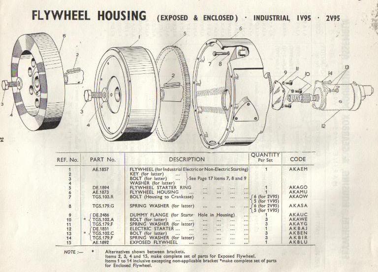
It was necessary to remove the flywheel and flywheel converter housing and replace them with the ones removed from the L40.
The YouTube link below, showing the engine running, is long over due for posting and is just something I never got around to.
Welcome to all visitors to this page, hopefully it will prove to be of some use to those of you trying to find out some information about the diesel engine products manufactured by the Turner Manufacturing Company Limited, Wulfruna Works, Villiers Street, Wolverhampton.
Initially my interest was in the two stroke diesels based on the original design by Professor Hans List at Jenbach, based in Graz, Austria. More recently this has expanded to include the four stroke diesel products of the Turner Manufacturing Company.

The L40/ L60 ENGINES
As I understand it the engine was originally developed by a firm of development engineers who are still in existence today, Jenbach of Graz in Austria, now known as Jenbacher Energiesystems and still going strong having apparently played some part in the development of the Land-Rover 200Tdi engine.
I spoke to a gentleman there around the year 2000 and he was able to advise that the engine was sold to Turner Manufacturing still requiring some development, they only ever produced a two cylinder version. He was also able to supply me with some information, including a photocopy of a manual in German which one day I'll have to get translated.
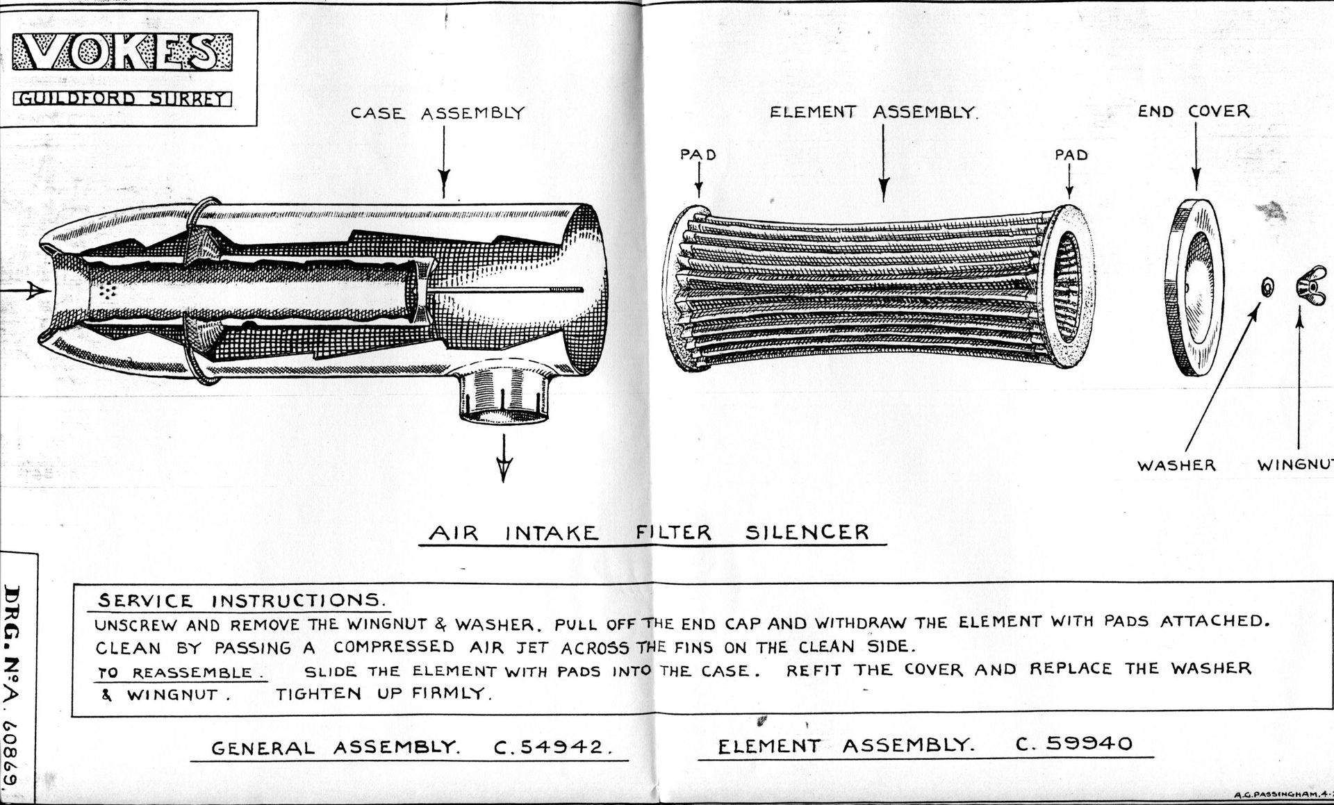
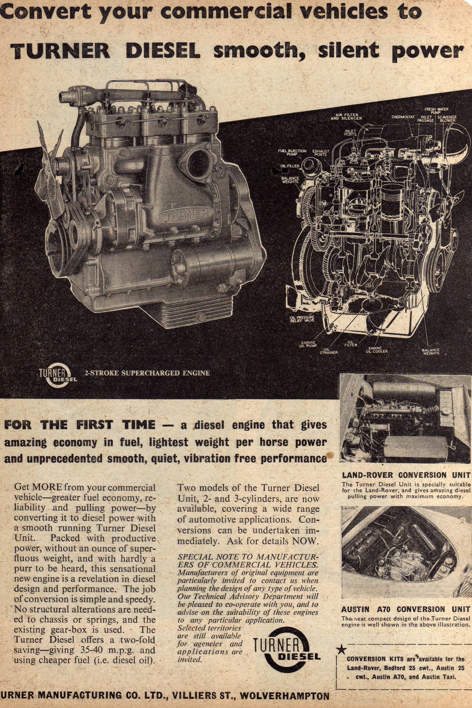
The whole engine is built largely of light aluminium alloy with internal ribbing for stiffness. The two cylinder version has a bore of 92mm (3 5/8") and a stroke of 105mm (4.13") giving a capacity of 1395cc (85.19 cubic inches) if the depth of the scavenge ports are ignored. It operates on a loop scavenge system, air being supplied via a filter to a twin belt driven Roots pattern three lobe blower (supercharger). This operates at 1.87 times engine speed and provides atmospheric pressure at 1000RPM increasing to 1.6ats at 3000RPM and provides air directly to shaped ports in the cast-iron cylinder liner (which incorporates water-cooled port bars and four sealing rings) without any crankcase compression.
Two columns of air, from opposite groups of ports, converge above the flat-topped, light alloy pistons to form a central stream which travels upwards, then outwards and downwards, forcing the burned gas through exhaust ports adjacent to the admission ports on one side of the cylinder.
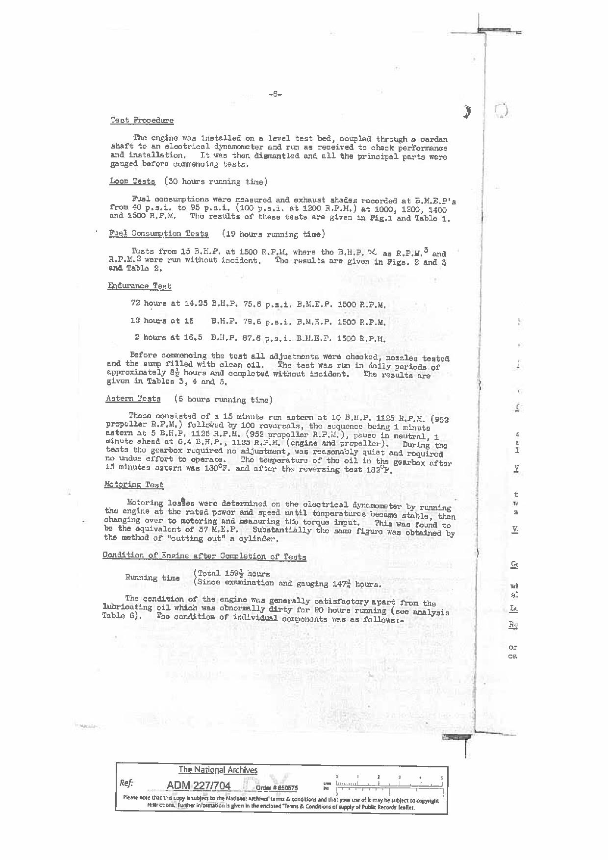
The pistons are of 'massive' construction and fitted with four compression rings above the gudgeon pin and two scraper rings in the skirt, the lower being of the oil control type. The top ring is wedge shaped with Ferrox inserts to give freedom from scuffing and to obviate the necessity of a fire ring (an anti-polishing ring leading to reduced lubricating oil consumption (If you read the British Admiralty report elsewhere on this site you will see observations about oil consumption during there testing of an 2V95 engine) and blow-by by preventing the build-up of carbon around the edges of the piston crown which causes liner polishing and wear).

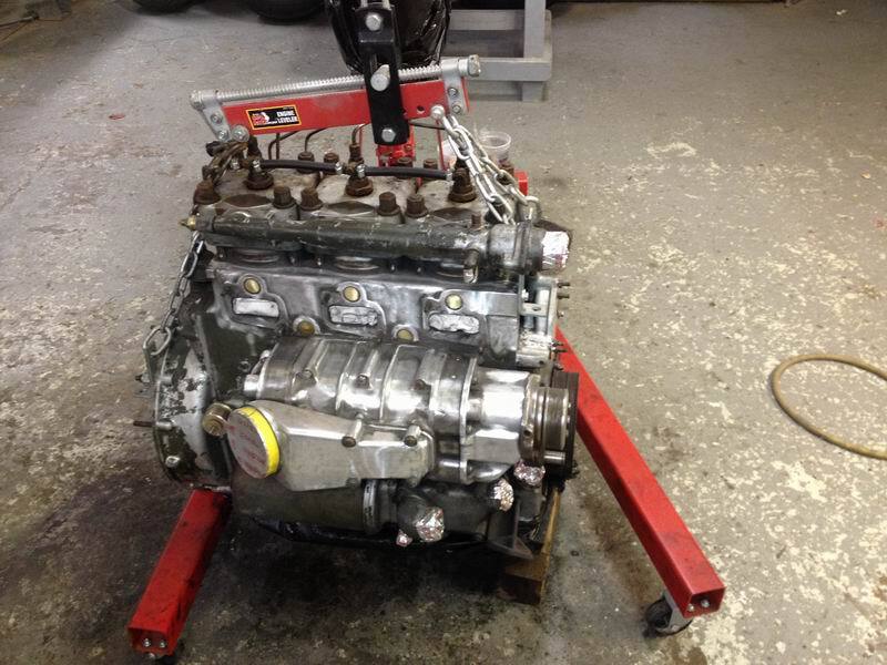
Turner automotive L60 3 cylinder inline engine

Side cross-sectional view of a Turner L40 engine.
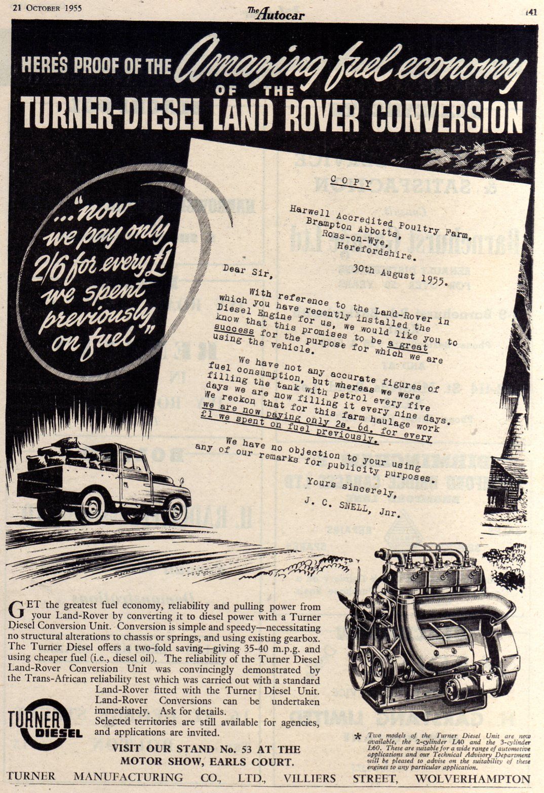
An undated advert lists the 2 cylinder unit weighing in at 340lbs (155Kg) whilst the 3 cylinder comes in at 450lbs (205Kg). It quotes 37.5BHP for the L40 (termed the 2L90) and 56BHP for the L60 (termed the 3L90) at 2800RPM. The power to weight ratio for the L40 is some 10lbs per bhp, the planned V4 version would have come down to 6lbs per bhp.
I'm no engineer, but it was said in technical press coverage at the time, that a two throw, three bearing, 180o crankshaft produced an unbalanced rocking couple. This was countered in this design by the existence of two oppositely rotating balance shafts carrying bob weights, mounted parallel to and driven from the crankshaft through the fuel injection pump gearing.
Specifically, a gear, mounted at the rear of the engine, in front of the flywheel, drives a pinion, which operates the double gear type oil pump. This same gear also provides the drive for the left hand side balance weight shaft, which, in turn, via the right hand balance weight shaft gear, provides the drive for the fuel injector pump.
To save weight the crankshaft journals are bored and both the big end bearings are also bored.
An article in The Motor of November 25th 1953 talks of a demonstration, in prototype form, of the new engine. Sample installations in a Vauxhall Wyvern and Land-Rover were already undergoing tests. It was reported that the engines would differ 'slightly' from the original List design (without detailing these differences).
The L40 was reported as being very compact with a three bearing crankshaft, the firing intervals being the same as on a four cylinder four-stroke engine. Primary balance being achieved by using rotating balance weights on a contra-rotating layshaft. There is a drawing in one Turner piece of advertising showing a glass of liquid sat on a cylinder head.
Full pressure lubrication is provided for the bearings and a Roots-type supercharger delivers air directly to ports in the cylinder liners without any crankcase compression being used. There are no valves in the engine, the exhaust timing being also by ports.
Built largely of light alloy, with internal ribbing for stiffness the engine was claimed to be more durable and economical than petrol engines although not so smooth or quiet - an unusually large bore exhaust pipe was necessary.
It was reported that designs also existed for a 60hp 3 cylinder in line, and 80hp V4 and a 120hp V6 (the latter never being known to have actually seen the light of day). The claim for 6lb of weight per BHP presumably applied to a figure for this V6. The smaller engine was quoted at 10lb per BHP.
The Commercial Motor of December 4th 1953 detailed the first commercial application of the L40 in a Land-Rover. It commented that proposed modifications to the governor drive would appreciably reduce the length of all the engines and would enable the three cylinder version to be installed in the engine compartment of a Land-Rover. Clearly Turner had identified Land-Rover as a significant market.
The British Diesel Engine catalogue for 1954 uses the word sensational to describe the new two stroke engine.

End view of L40 Engine
A restored L40 engine
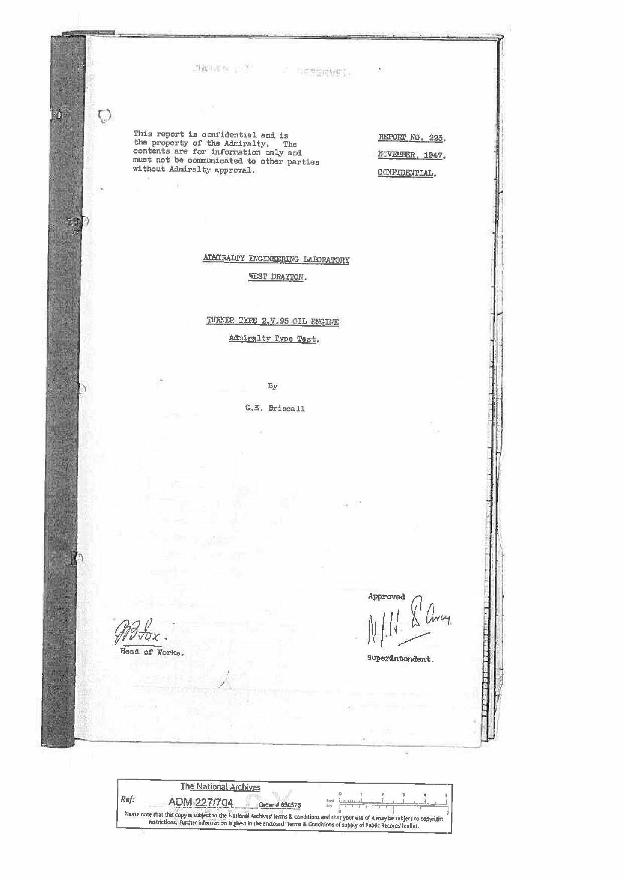
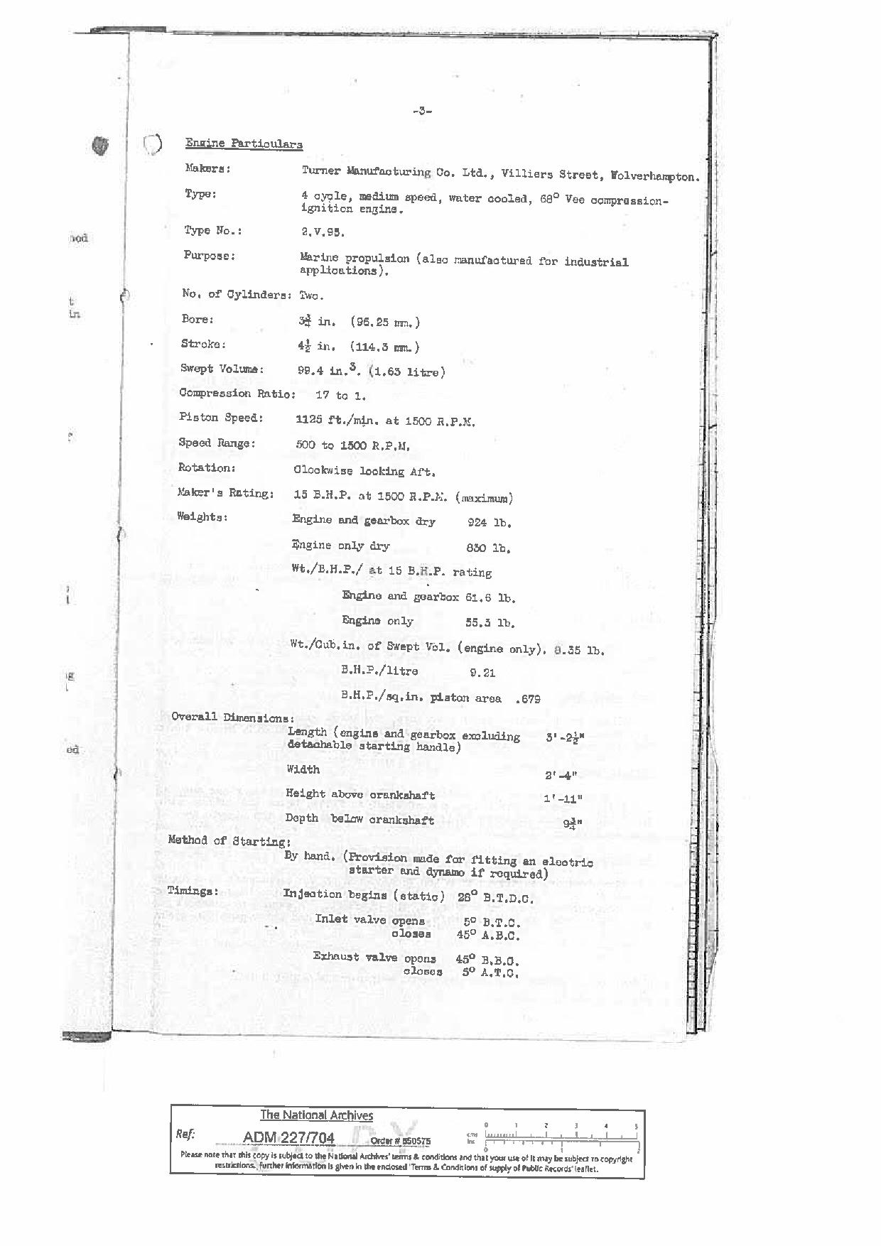
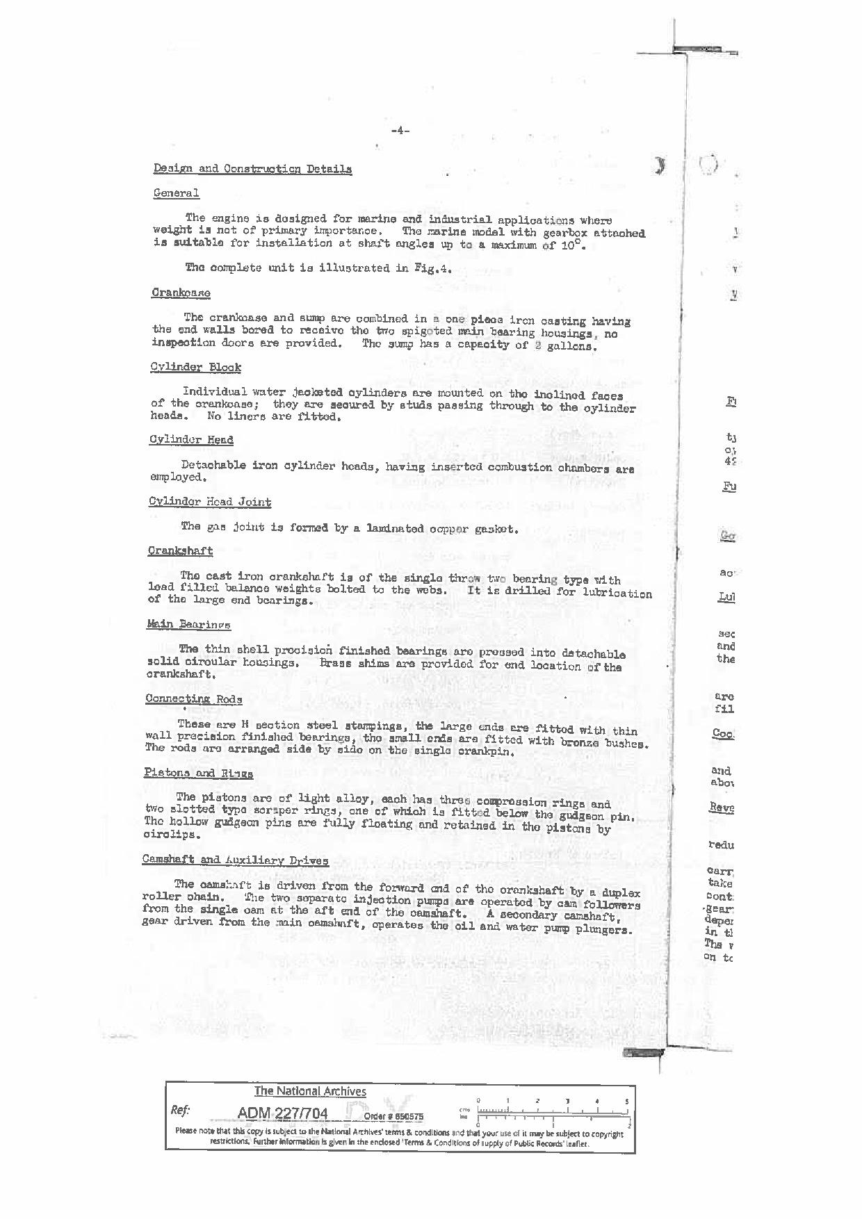
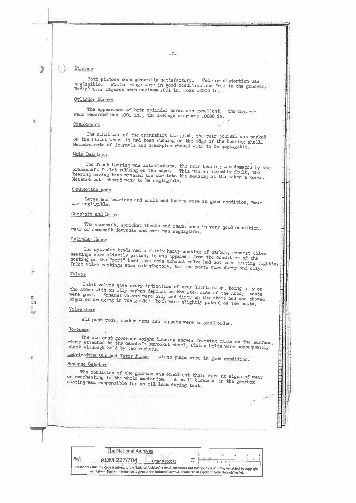
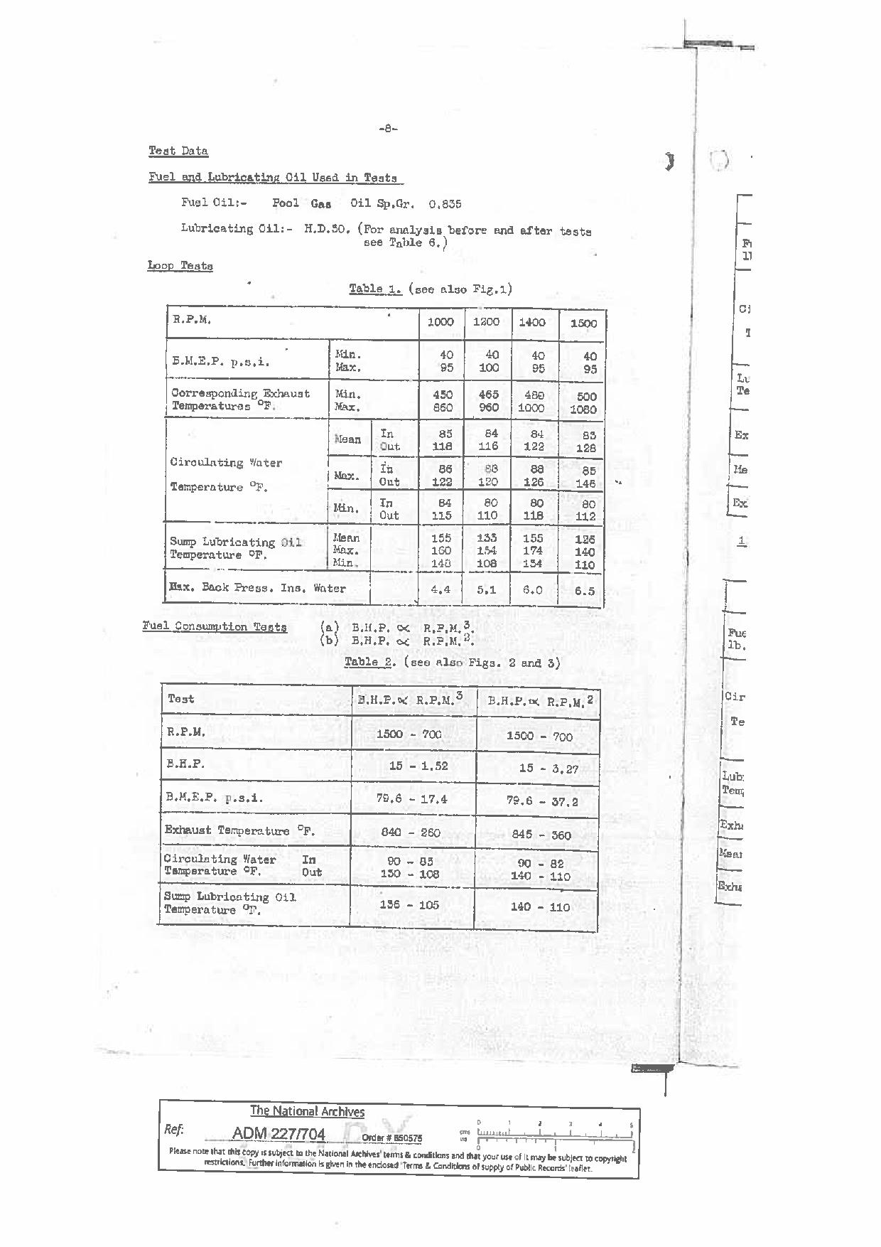
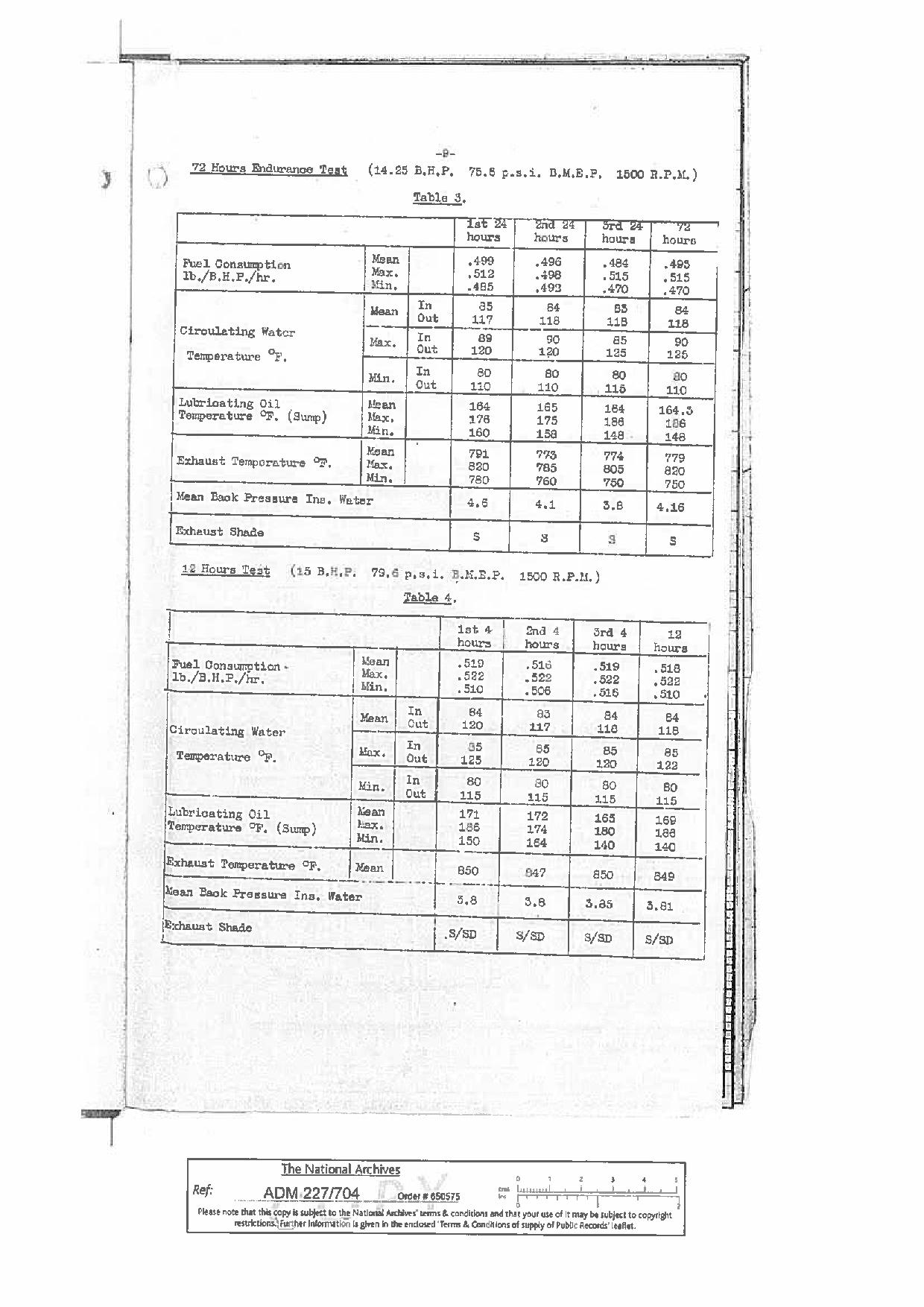
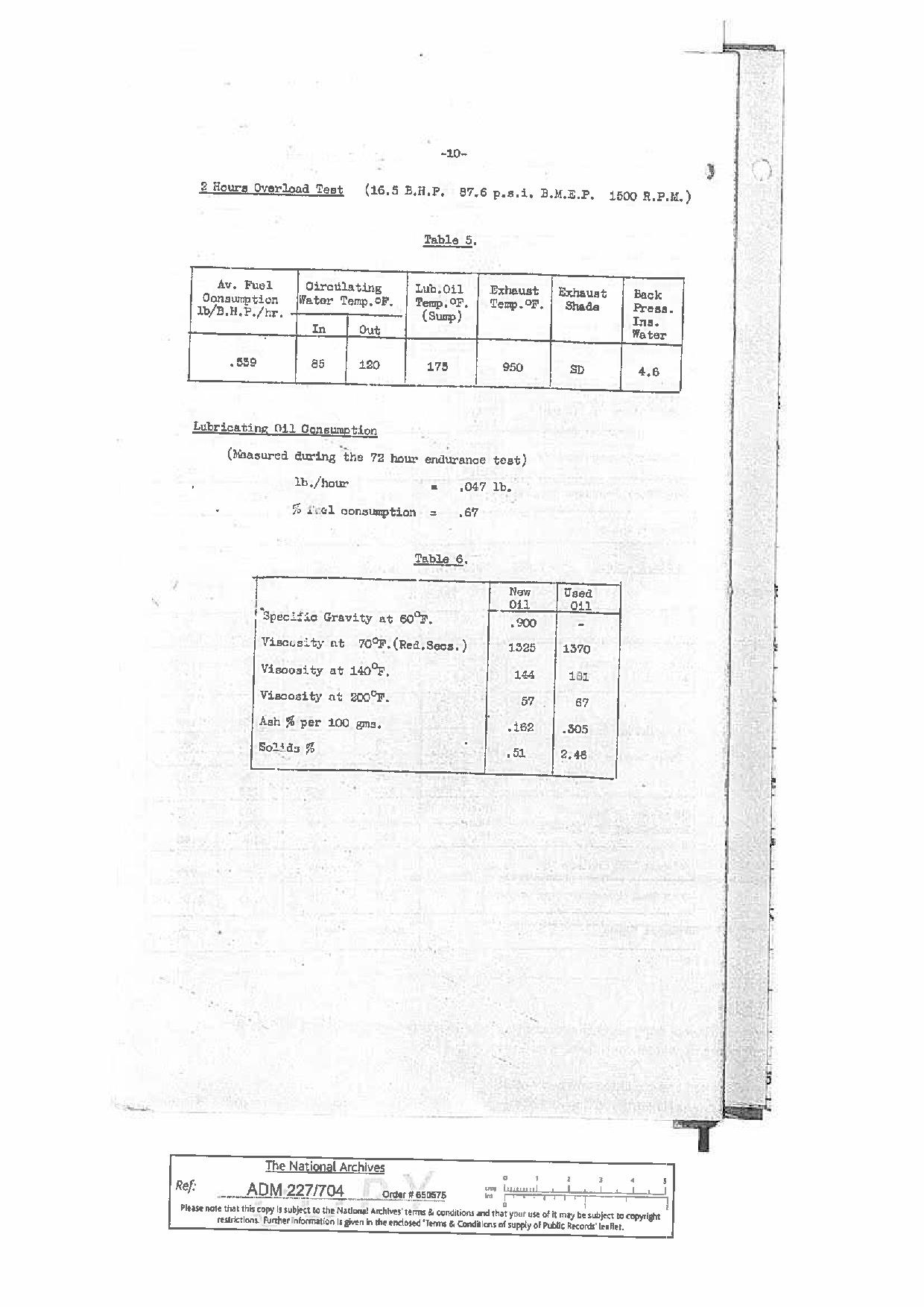
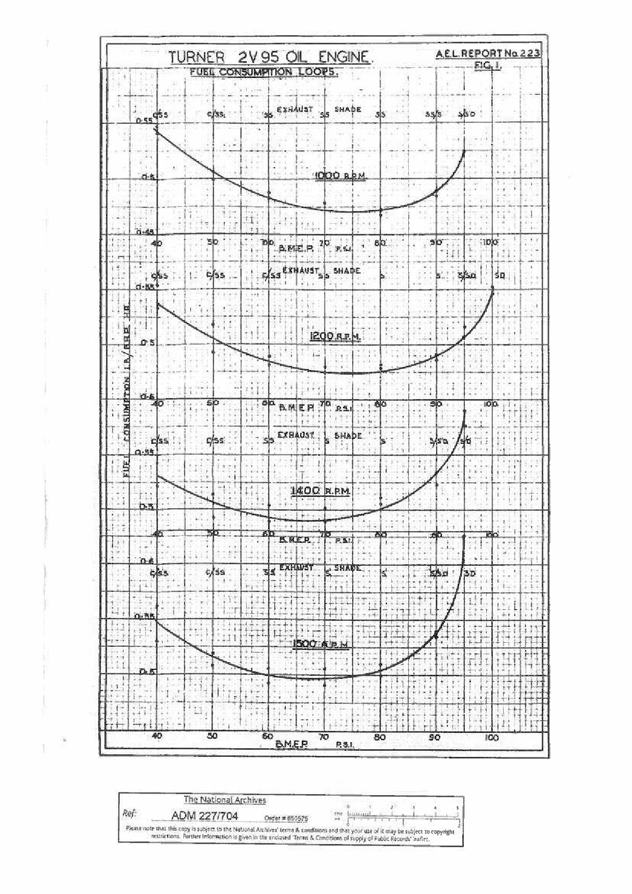
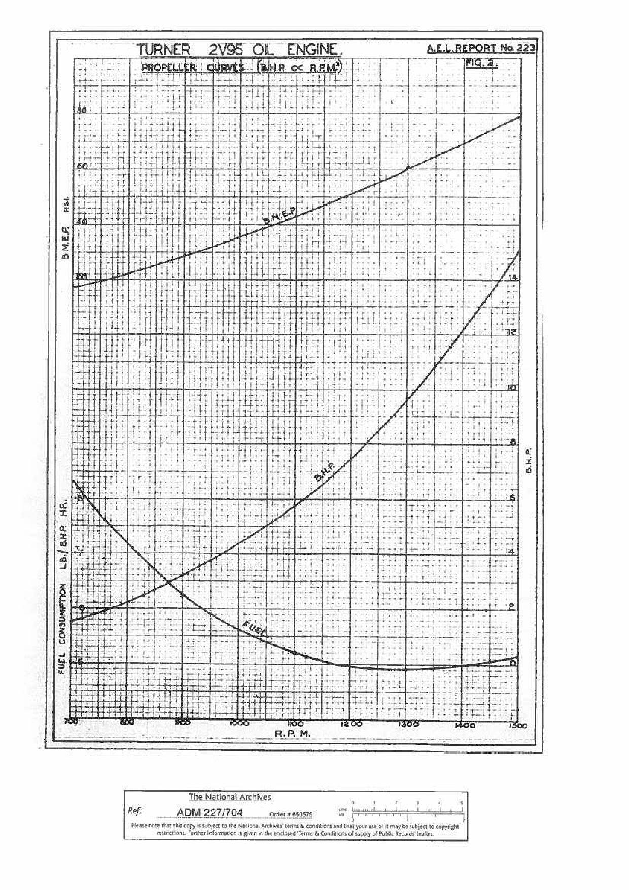
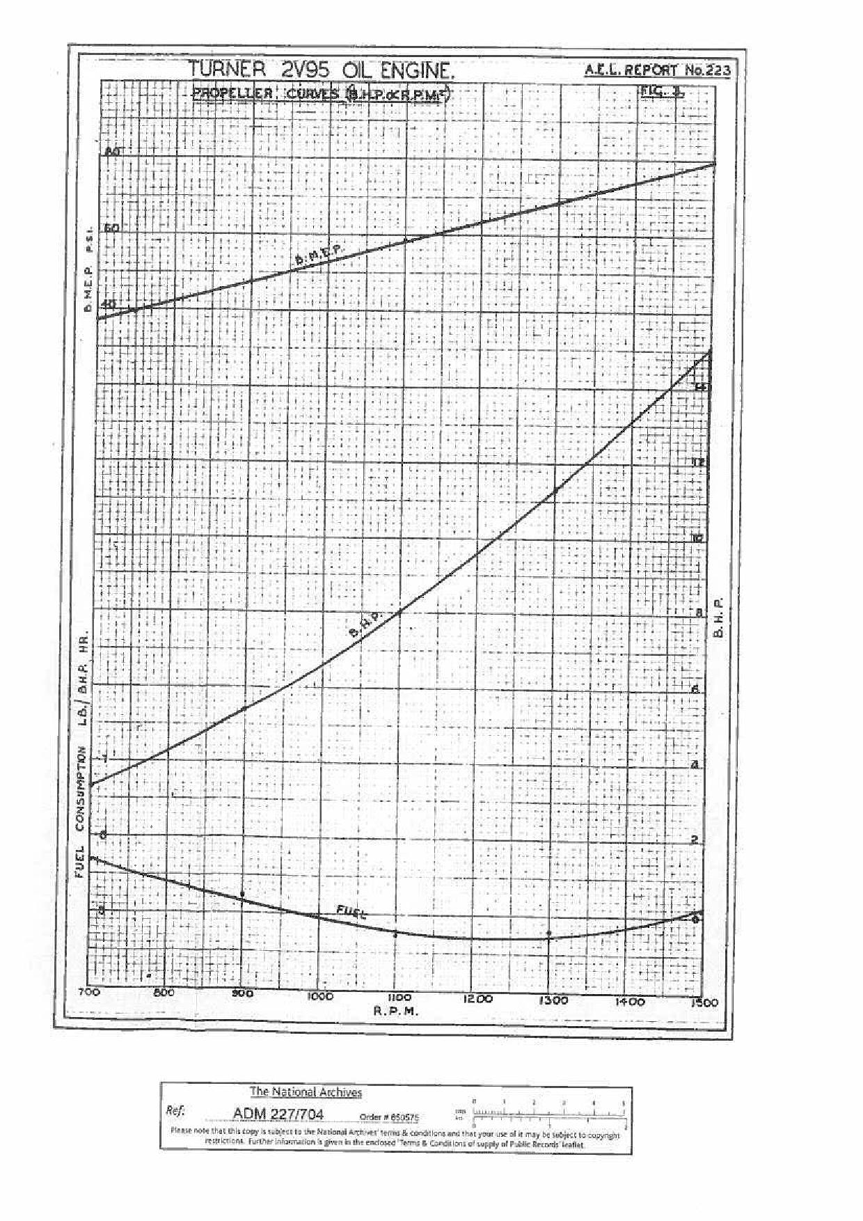
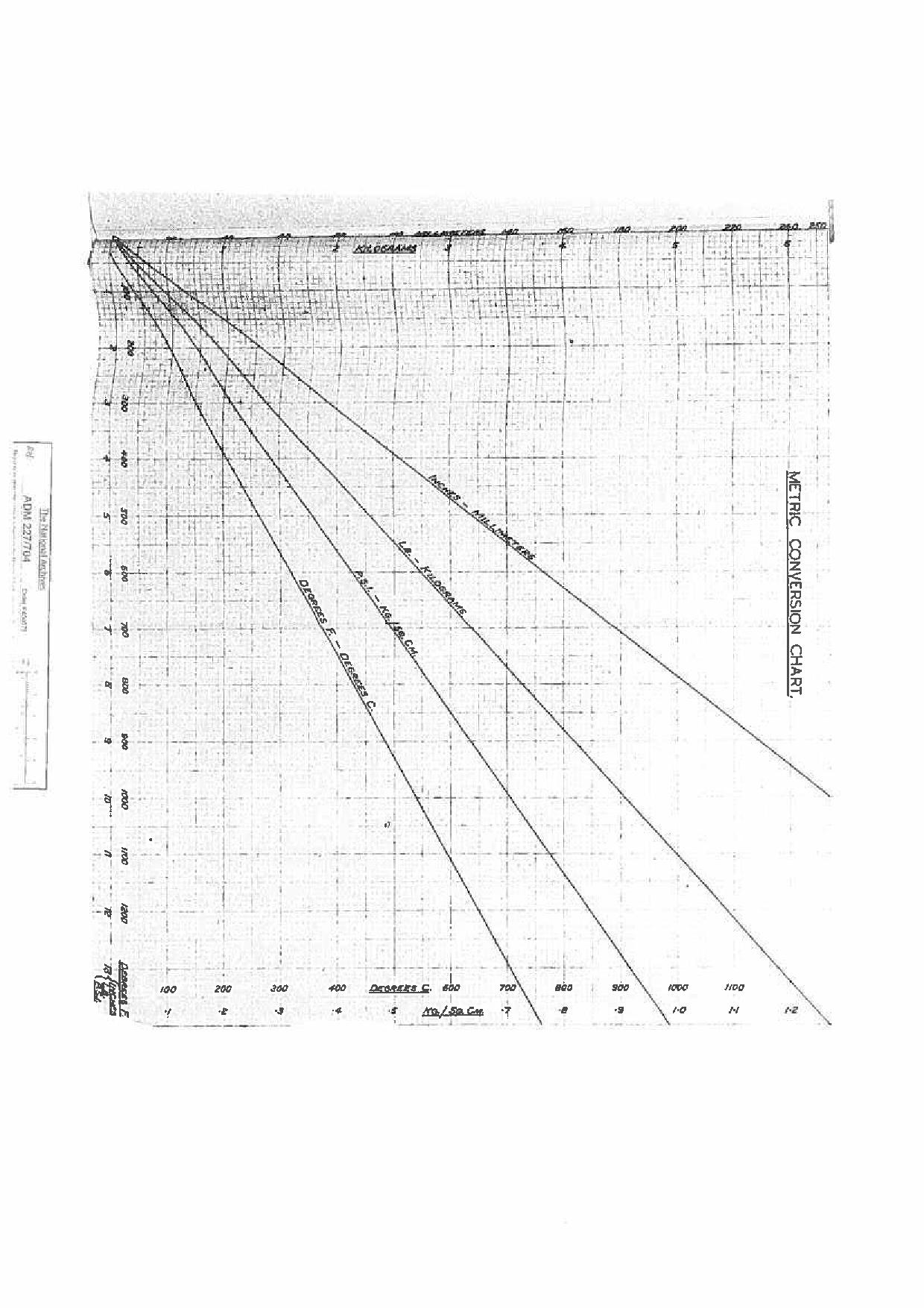
This next series of images are of a British Admiralty report in to a Turner 2V95 engine.


First and foremost my principal interest lies with early Land-Rovers, however I have a particular leaning to the more unusual versions.
I first became aware of the existence of such a beast as the Turner two stroke a number of years ago, when an acquaintance of mine, who had been into Land-Rovers a good few years longer then me, told me in passing that he had a two cylinder unit.
It was some 4 years later that the lump came into my possession having patiently bided my time. I have yet, and over 30yrs has lapsed, to examine what I bought that day, it is still sitting out in the shed along with a cracked fuel injector pump casing and a box of bits.
Since becoming interested I have tried a wide range of avenues in an attempt to find out more about the company. I have come to the conclusion that whilst they may well have received some press coverage in their day they can't have been too successful judging by the widespread lack of knowledge in existence today.
I've very recently (31st May 2018) became aware of a posting made in January 2015 as follows:-
Obscure bit of history I suppose, but might be of interest to someone. Have discovered that the RLC archive website allows you to list the various Land Rover contracts and sub-contracts, and by searching for make Rover and Keyword Rover I spotted an order for a 109" pick-up with 2-stroke diesel engine. That was in June 1957. As I have paid to view stuff on-line I can see the ledger page which says it was standard 109 pick-up, then a contract to Turner to install a 3-cylinder L60 2-stroke - no specifics of the vehicle. The original petrol engine valued at £135 was to be returned to the Ministry of Supply.
Unfortunately no other information is known at this point.
There are, however, a band of people out there, who are interested in these units. I don't pretend to have found them all, hopefully this Web Page will bring in a few more.
A way back in April 1999 I was aware of the existence of only 6 units, I owned two (an L40 and an L60), one up in Durham (an L40) and three belonging to another guy (an L40 and two marine L60's). (The known number has now increased somewhat).
Having obtained the L40 unit I had always planned to install it in an 80" wheelbase Land-Rover as a curiosity item when time permitted. Ironically having obtained this unit I became aware of a guy who had a total of 4 units who I went to see. At this time he wasn't particularly minded to sell.
A year later he had changed his position and wanted to sell the L40 unit he had, but by now I had decided I wanted the L60 he owned. Some time later he had changed his mind again and was prepared, for a fair price, to sell the L60 to me, so he then had the 3 units left and I had two.
Some time later this same person was now considering selling the other three units as a job lot. As they were a valuable source of very rare spares I'm just had to bide my time.
Having obtained the engine I wanted I then had to find a suitable host vehicle, there was no way it would fit into an 80" Land-Rover. I had seen a suitable vehicle, an 88" Series One, some years previously but assumed it may have been sold, as luck would have it it was still there although the owner had started a rebuild. Fortunately he was minded to sell it, so I then had the vehicle into which to put the engine.

Through a person who supplies some Turner spares and is, I believe, the unofficial Turner Register Spares person, I found that there is a another person (who used to work for a branch of what was Turner and who is very interested in the products of the Turner Manufacturing Company). He has been able to retain some original drawings that were due to be thrown out.
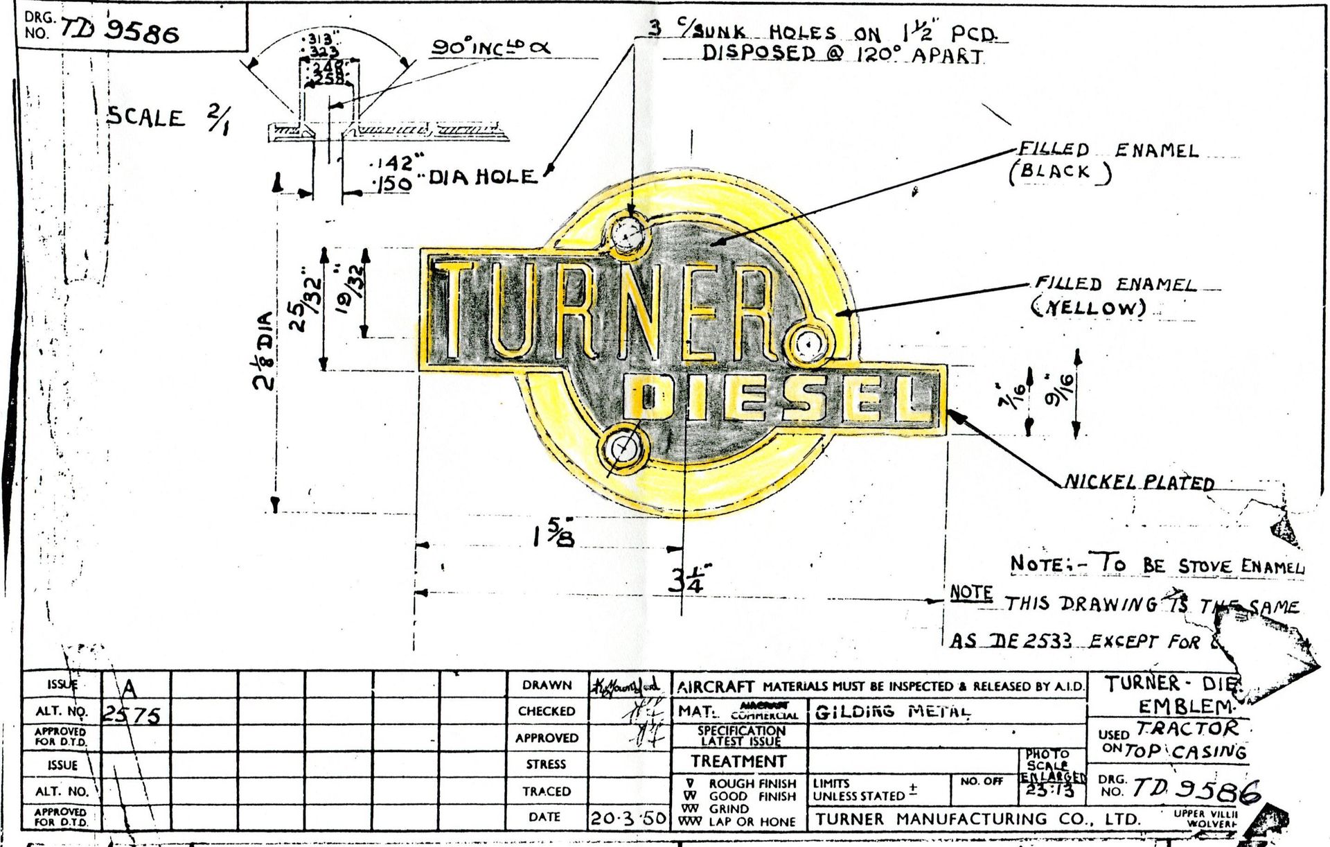
He was able to supply me with copies of original drawings of the exhaust system so that I can get them manufactured as well as a plan of the Turner Diesel badge. I did investigate the costs of having this re-manufactured but the cost was prohibitive with so few potential customers.
The exhaust for the Land-Rover consists of two 'boxes', one 30" and the other 18" long, both 5" in diameter, with 8 1/4" by 2 3/8" diameter tubes each end and connected by flexible piping and the front section is a length of 3 1/8" flexible brazed to the exhaust manifold.
The vehicle was up and running, after a fashion, for the Festival of the Plough event in September 1999 which marked the 50th Anniversary of the Turner Yeoman of England tractor.
I have been advised that it is believed, given the registration of the vehicle in the video, and the location detail that the car came from the Central Garage Church Stretton which was a Turner dealership. This garage still exists and parts of the road shown match the old route of the A49 before the bypass.
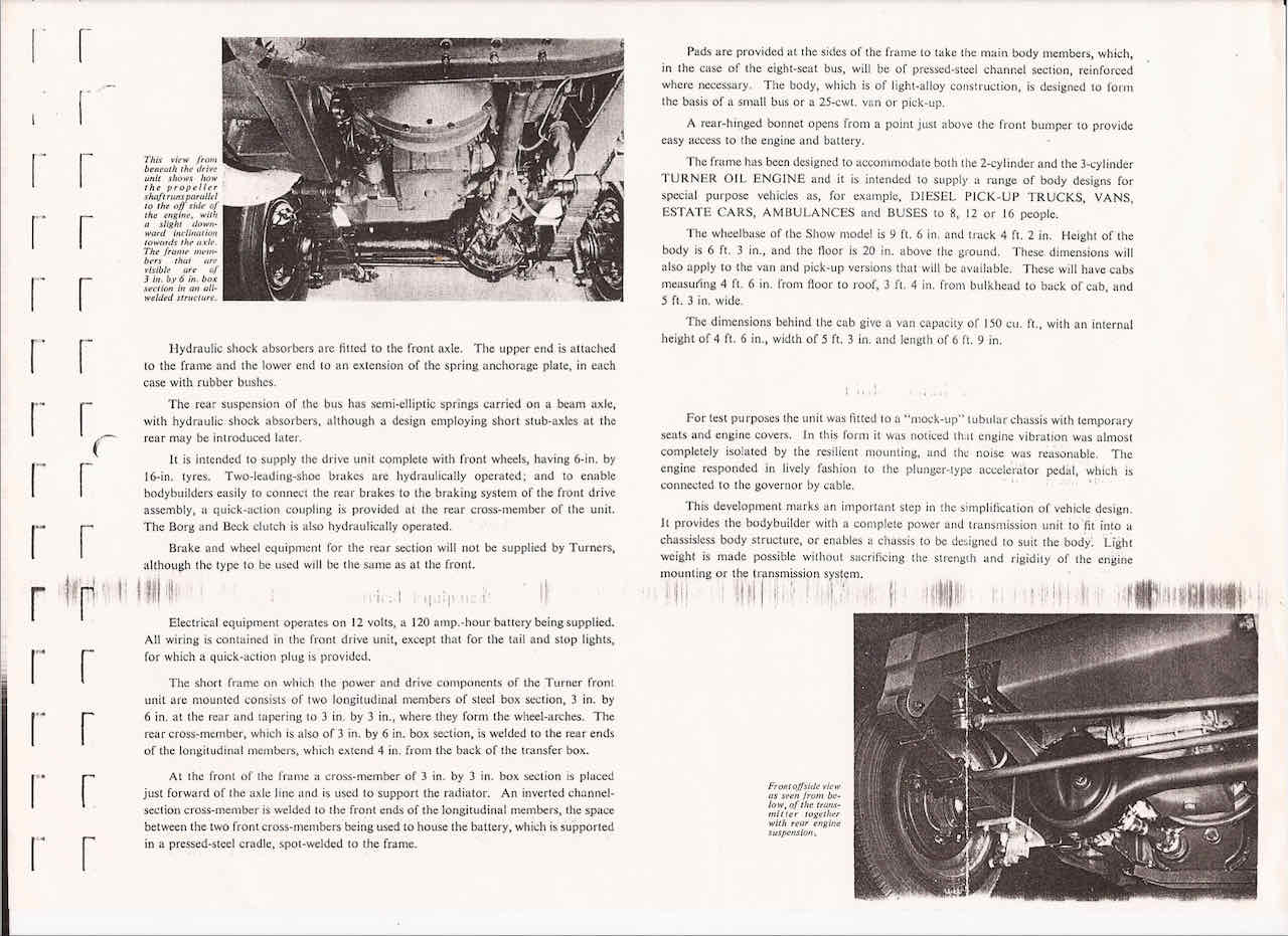
FRONT WHEEL DRIVE UNIT
The development of a front-wheel drive chassis-less light vehicle by Turner was detailed in the Commercial Motor of September 3rd 1954 stating that James Whitson had been asked to build a prototype eight seater bus. It was said that by slight re-arrangement of the engine position it would be possible to accommodate the L60 version with the intention of a 16 seater bus.
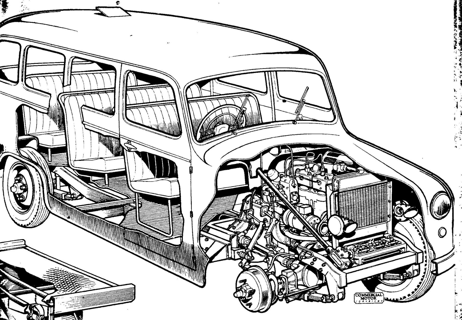
As a Land-Rover person I can't help noticing a number of very Land-Rover like features in the chassis and layout, the fact that the track is given as 50" and the front wheels being 6.00 x 16" would seem to support this.
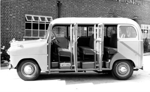
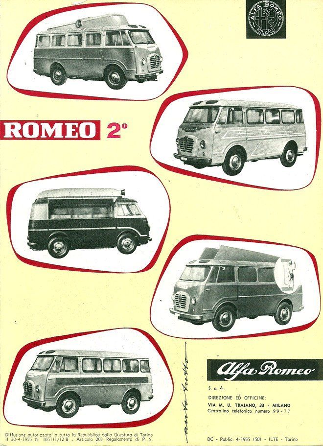
The Commercial Motor of September 24th, 1954 gives details of a front-wheel drive eight seater bus using the two cylinder Turner unit driving through a four-speed gearbox which appeared at that year's show. James Whitson And Company Limited of West Drayton, Middlesex, built the bus body.
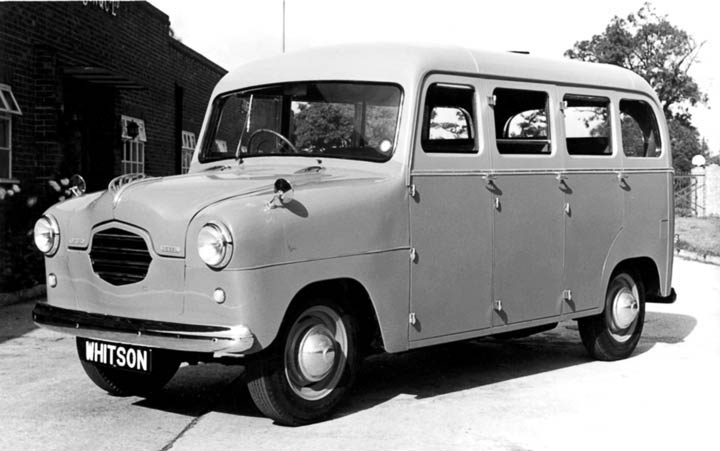
The vehicle is bit of an 'odd' shape I don't think the overall project was a raging success, having said this it would be interesting to know if somebody has this tucked away at the back of a shed.


The Commercial Motor of 21st September 1956 reported that Turner produced a 'last minute surprise' at the Commercial Motor Show that year when they displayed a milk-delivery vehicle. They noted that whilst the front end was similar to bus above 'the chassis has a number of original features, including a Manumatic semi-automatic gearbox control and rear suspension units based on rubber elements'.
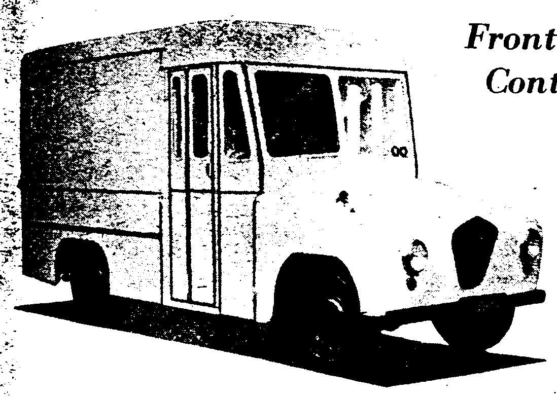
The Manumatic control was produced by the Automotive Products Company Ltd. (later known as AP) and was similar to systems fitted to private cars. Check out this link which describes the system as fitted to Austin vehicles as a pre-cursor to the unit eventually fitted to the Mini. Vacuum for the servo mechanism was provided by an aircraft-type pump (presumably an in house design as Turner Manufacturing made such devices as detailed on the Other Products page).
The engine was an L40. The combination of front wheel drive and the independent rubber springs at the rear enabled the floor height to be reduced to 1ft 6" (46cm) and provide room for underfloor lockers.
The Manumatic system gave two pedal driving capability and simplified gear changing by automatically synchronising engine speed with output RPM.
The clutches of the centrifugal type and incorporated a simple synchronising element comprising of a friction driven contact ring which increased or decreased the engine RPM to match the road speed. The gear lever was fitted with a switch which was hand operated and, when 'energised' operated a solenoid controlling the servo vacuum disengaging the clutch during a gear change.
The vehicle had a four speed all synchromesh gearbox.
The rear suspension were Andre-Neidhart rubber elements with trailing links on which the wheels were mounted. Advantages claimed were low cost and improved cushioning.
The panelling for the show model was aluminium with the intention for fibreglass to be used in production.
It was also reported that a Turner four-wheel-drive pickup was also available for inspection which was powered by the L60.
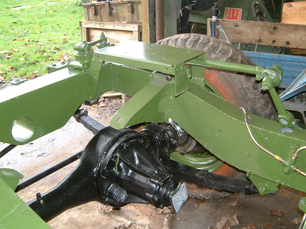
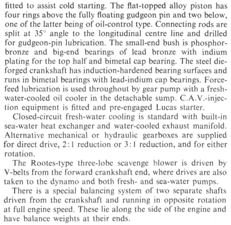
A TURNER ENGINED LAND-ROVER CHASSIS
A recent member of the Land-Rover Series One Club posted he had acquired a vehicle which had previously been fitted with a Turner engine.
The first picture below shows that the original engine mounts have been removed and the Turner supplied items welded in place. It also shows the cut-out in the flywheel crossmember to make way for the pre-engaged starter.

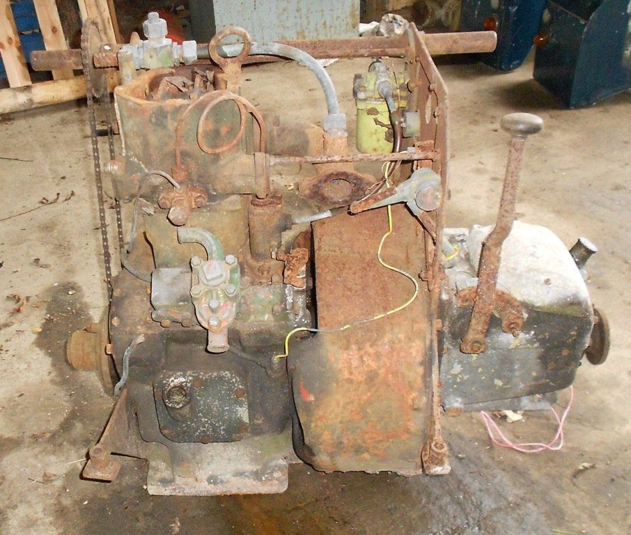
The next picture is a close-up of the recess mentioned above.

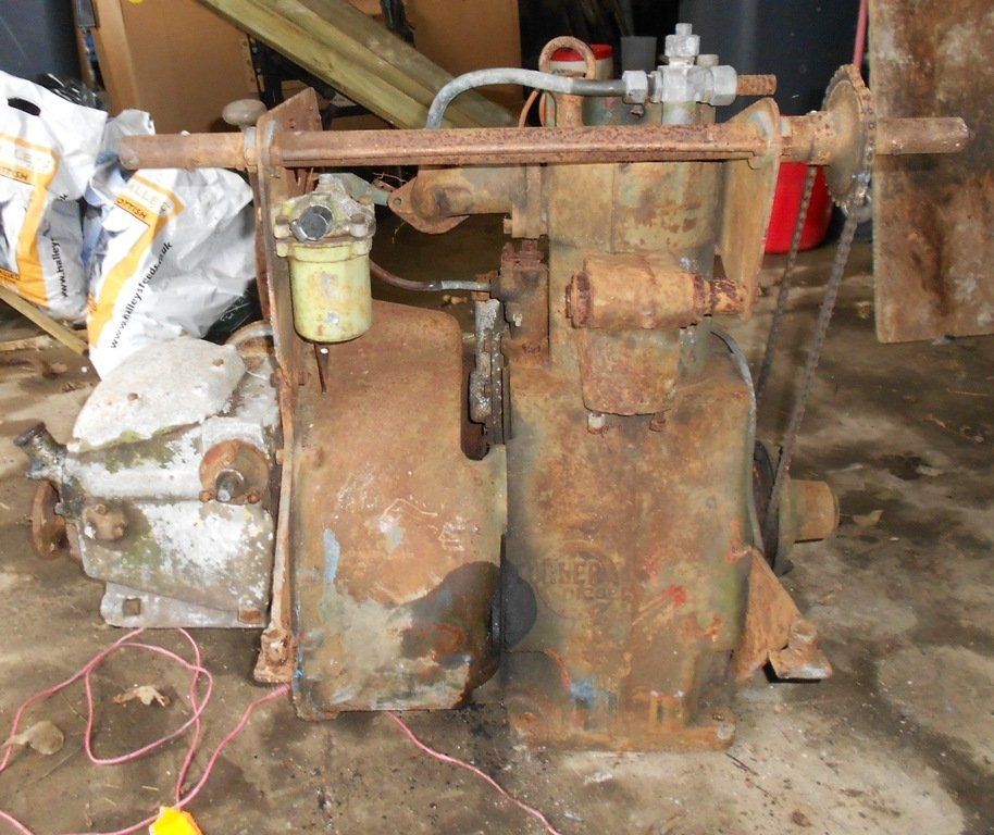
The last picture shows a couple of things you probably wouldn't appreciate unless you had actually installed an engine yourself. The first is that the battery tray as it is would have interfered with the dynamo and you need to make changes to accommodate this.
Secondly if you look carefully at where the paint run is on the differential you will see that the stiffening web is actually ground down as recommended in the Turner fitting instructions to avoid impact with the sump.
GENUINE 80" LAND-ROVER TURNER PARTS
The following two pictures come from an 80" Series One Land-Rover which was also the source of one of the two L40's I own.

Items of note in these two pictures are the special radiator cowl and the two hoses, the bottom one is definitely a special. Also note the plate on the wing which is a genuine plate which we believe was supplied as a part of the kit Turner supplied.
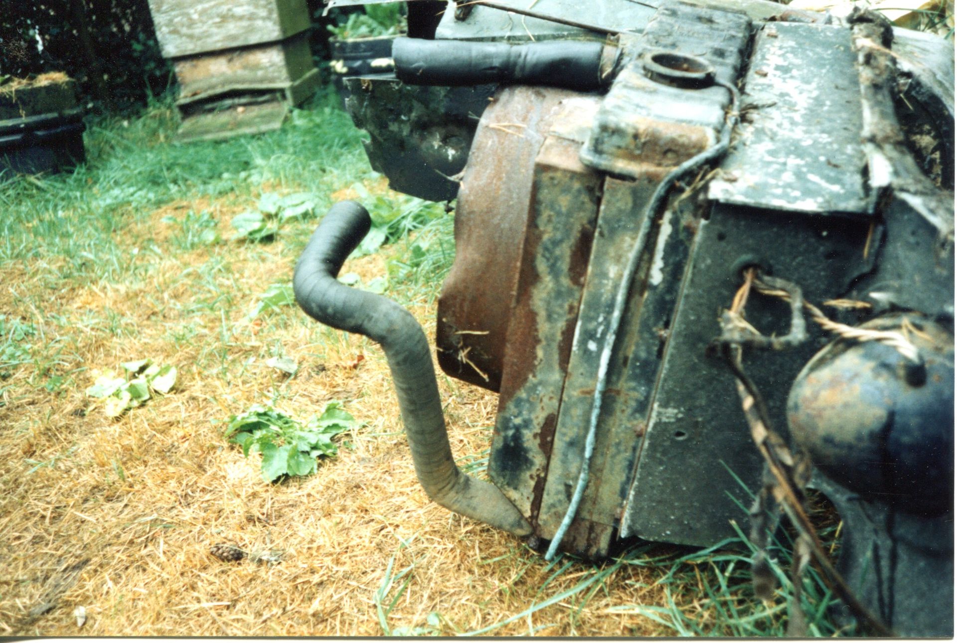
Unfortunately since these photo's were taken the owner cannot recall what happened to them. If anybody out there currently owns these parts or anything similar please get in touch.
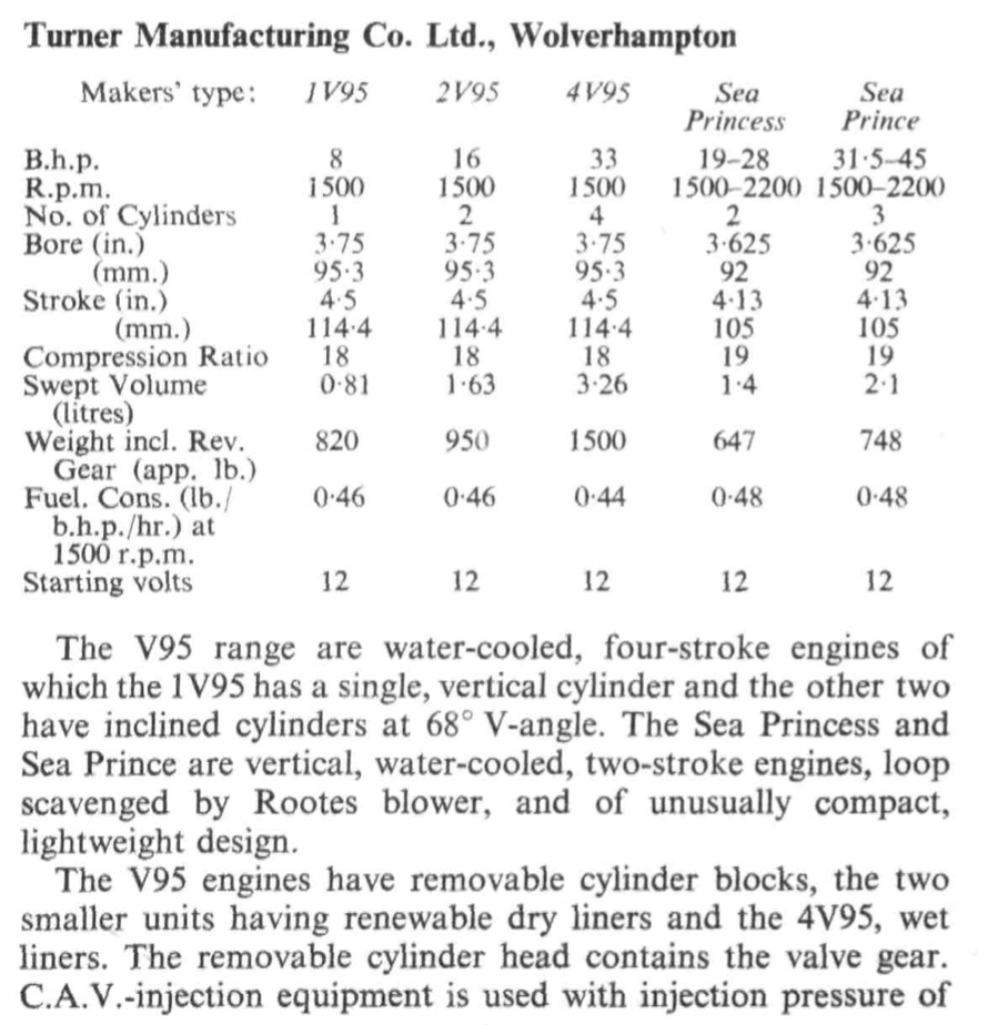
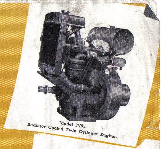
V95 SERIES DIESELS
The best known application for the V95 series diesels was in the Turner Yeoman of England tractor. I believe it can lay claim to being the first UK diesel powered tractor with an in-house produced engine.
However, production of these engines in single, V-twin and V-four engines variants started in 1946 having been designed by J Malcolm Robson, formerly of Fowlers. The combustion chamber was to a Freeman-Sanders patent. The engines are 3.75inch bore by 4.5 inch stroke with a nominal output of 7.5 to 9 HP per cylinder dependant on duty cycle rating.

The first version of the engines had a patented groove in the top of the piston claimed to improve combustion. For the tractor production in 1949 the engines were uprated and designated as the MK2. Later in tractor production a revised cylinder head and wet liners were introduced with the engine being designated the MK3. So the MK2, MK2A and MK2B tractors have the 4V2 prefix to the engine serial number and the MK3 tractors, from serial number 900, have the 4V3 prefix.
They were originally intended for marine use which may account for the strange choice of 68 degrees for the V angle. They were certainly used to power the first Norfolk Broads cruisers to use diesel power. It is known that a pair of 4V95 engines were fitted to the Admiral's Barge in Brazil.
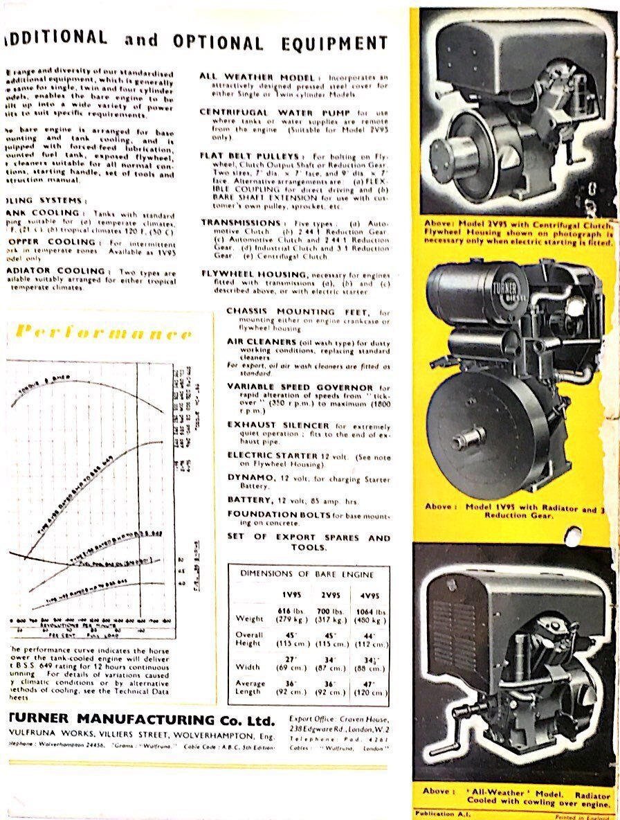
They were sold for a multitude of industrial uses with the factory producing or fitting electrical generating sets, pumping sets, over-centre clutches and belt pulley drives. They were available with radiator or syphonic cooling.

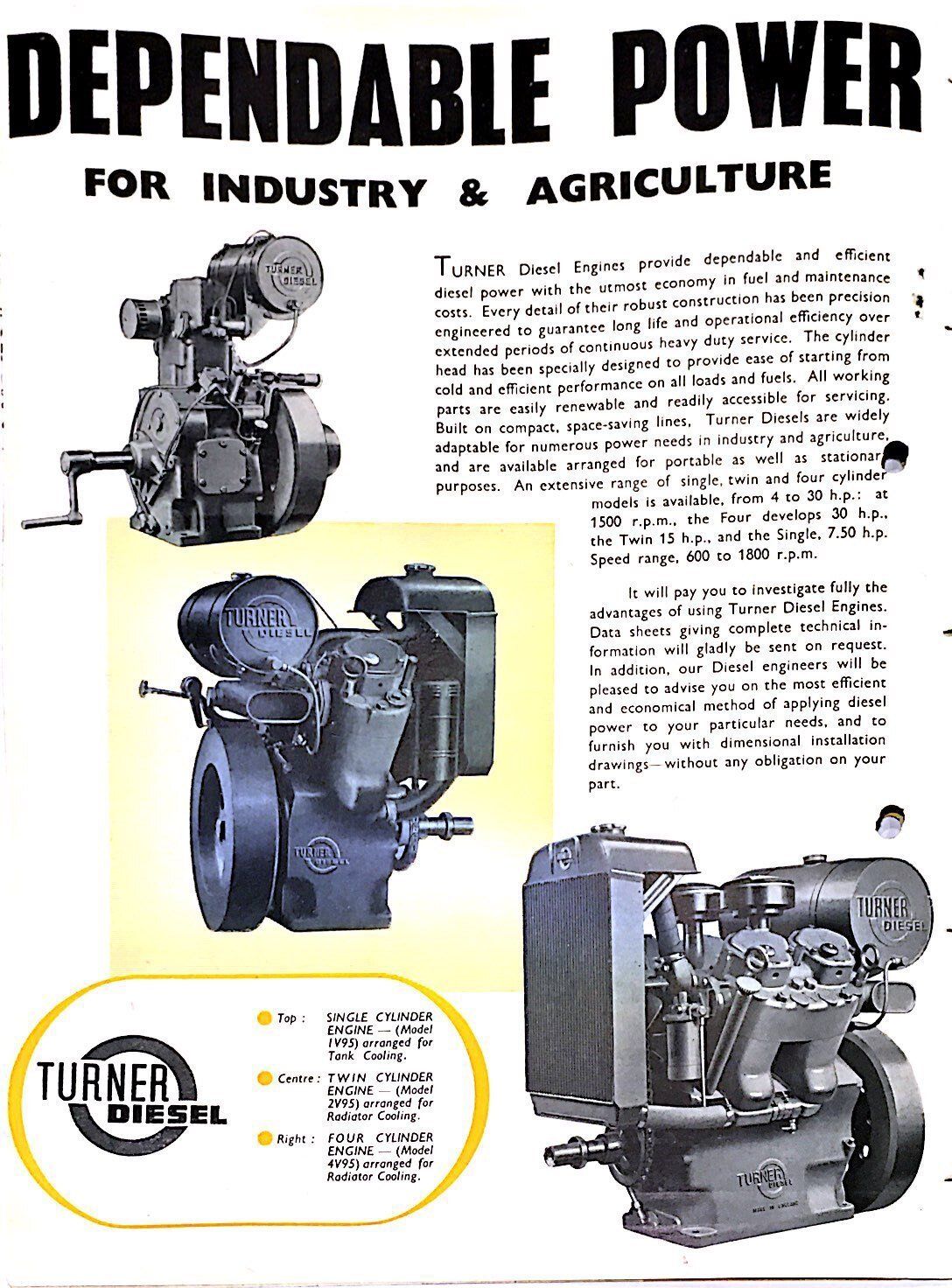
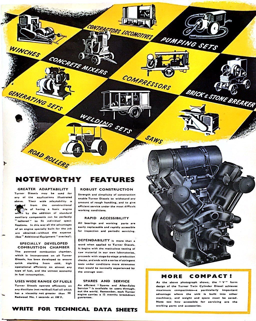
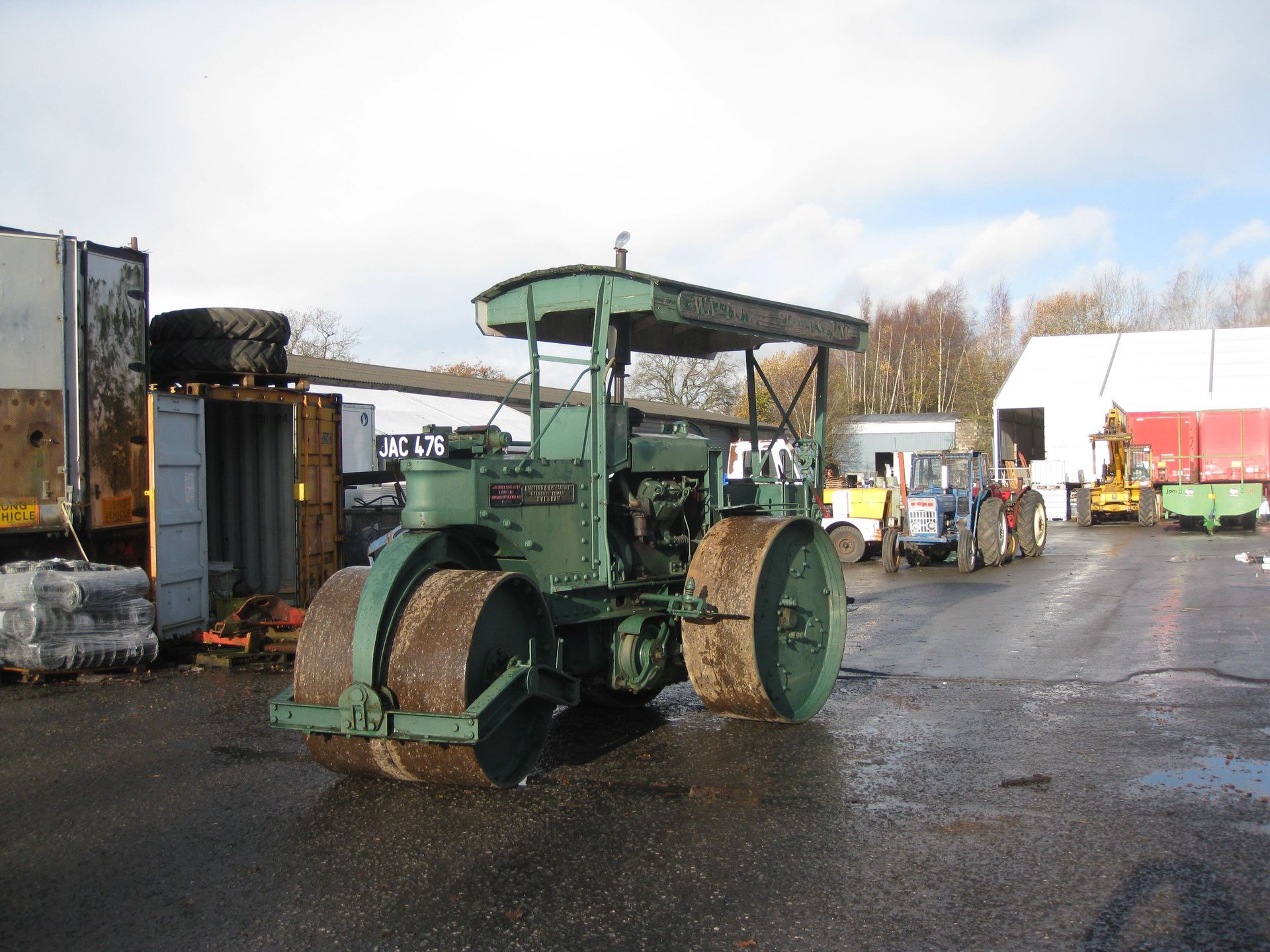
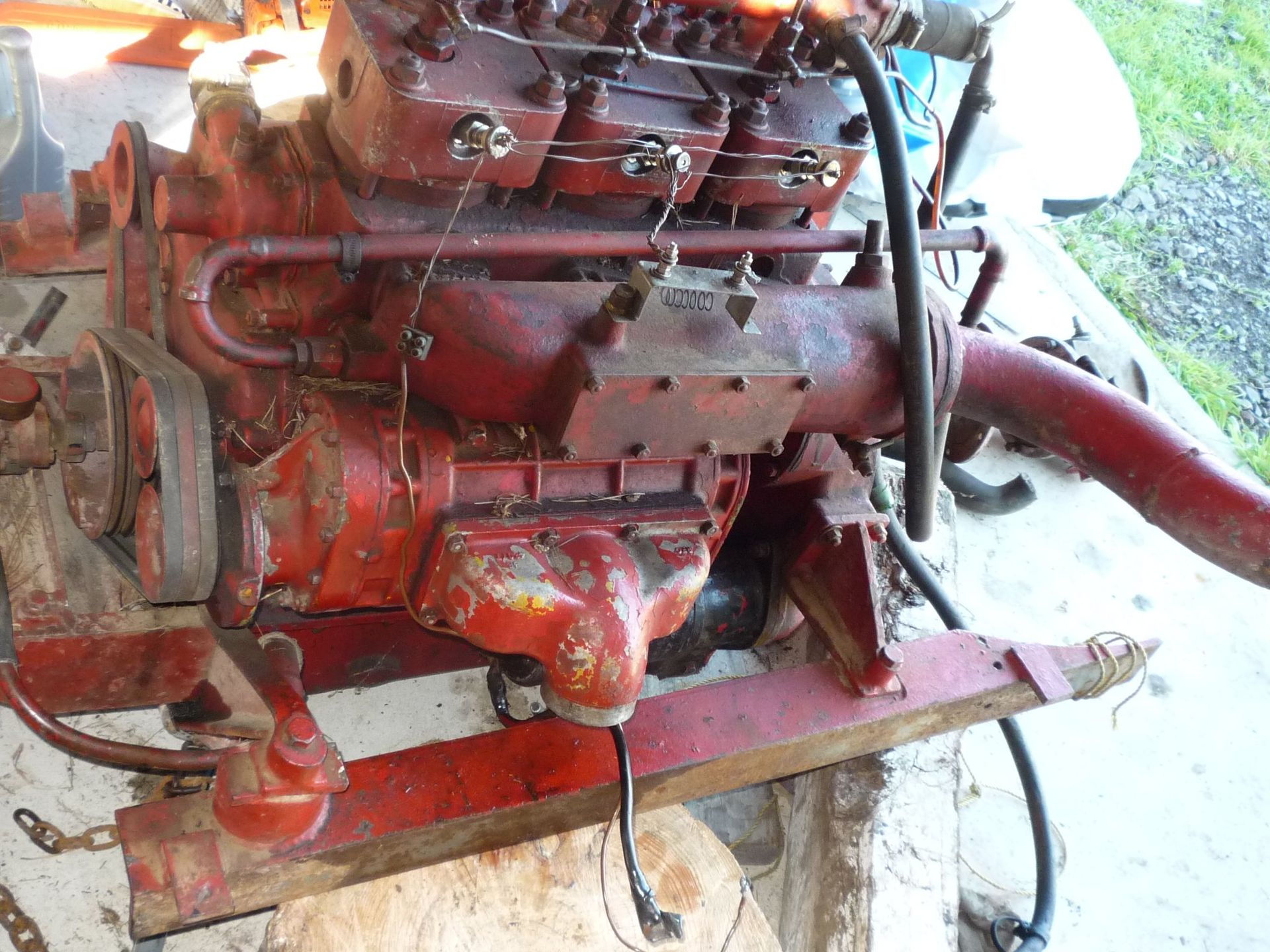
V95 engines were used to power machines such as Marshall Road Rollers, Jones Cranes, and Planet Hibberd tugs.
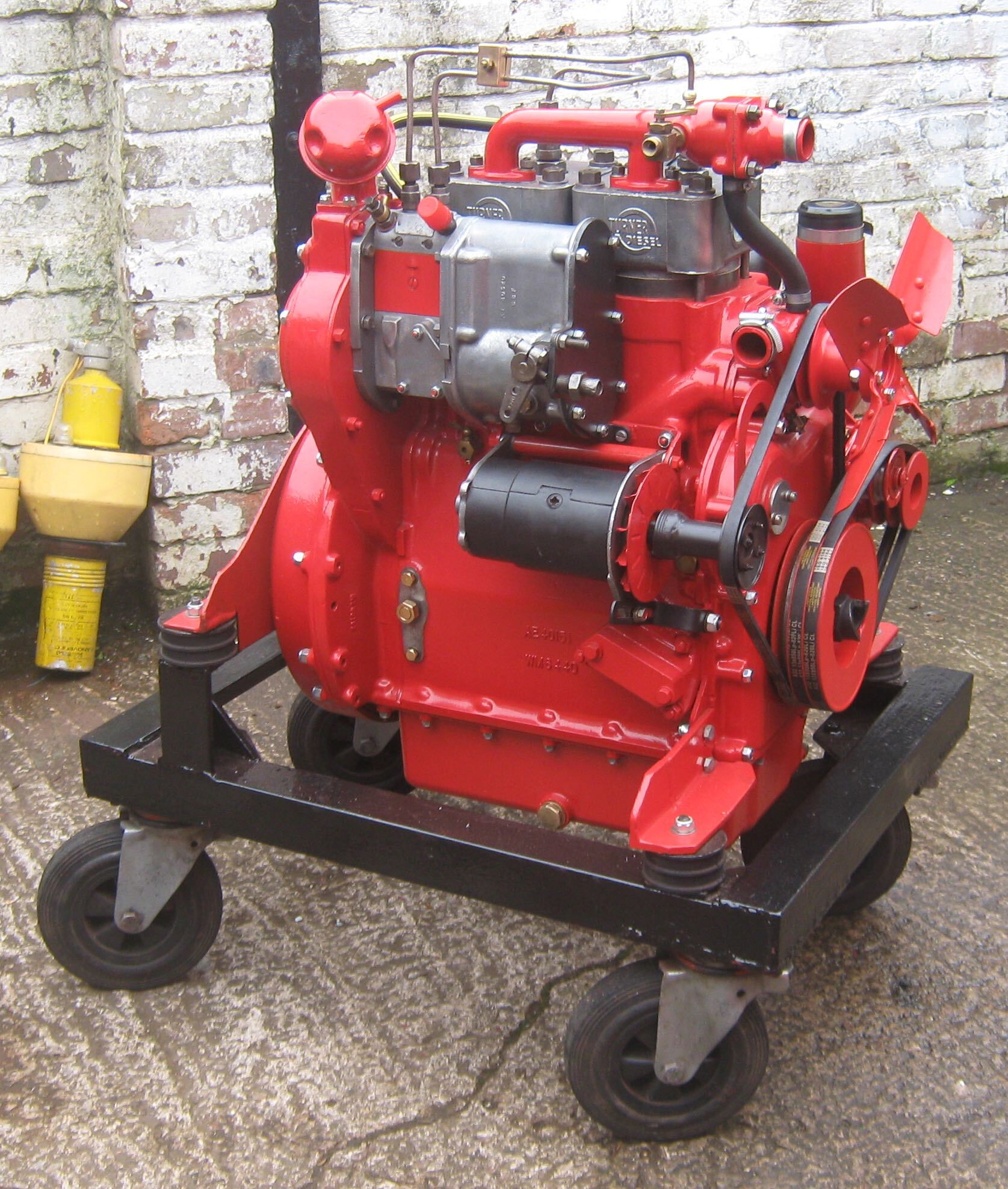
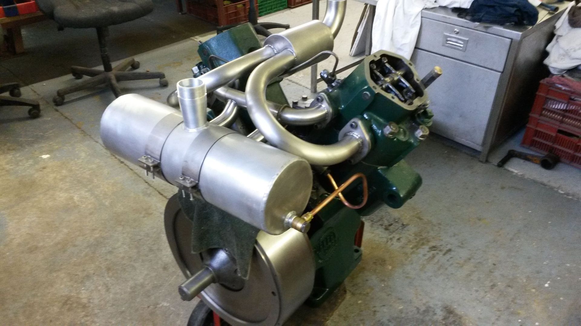
Close up of 4V95 engine
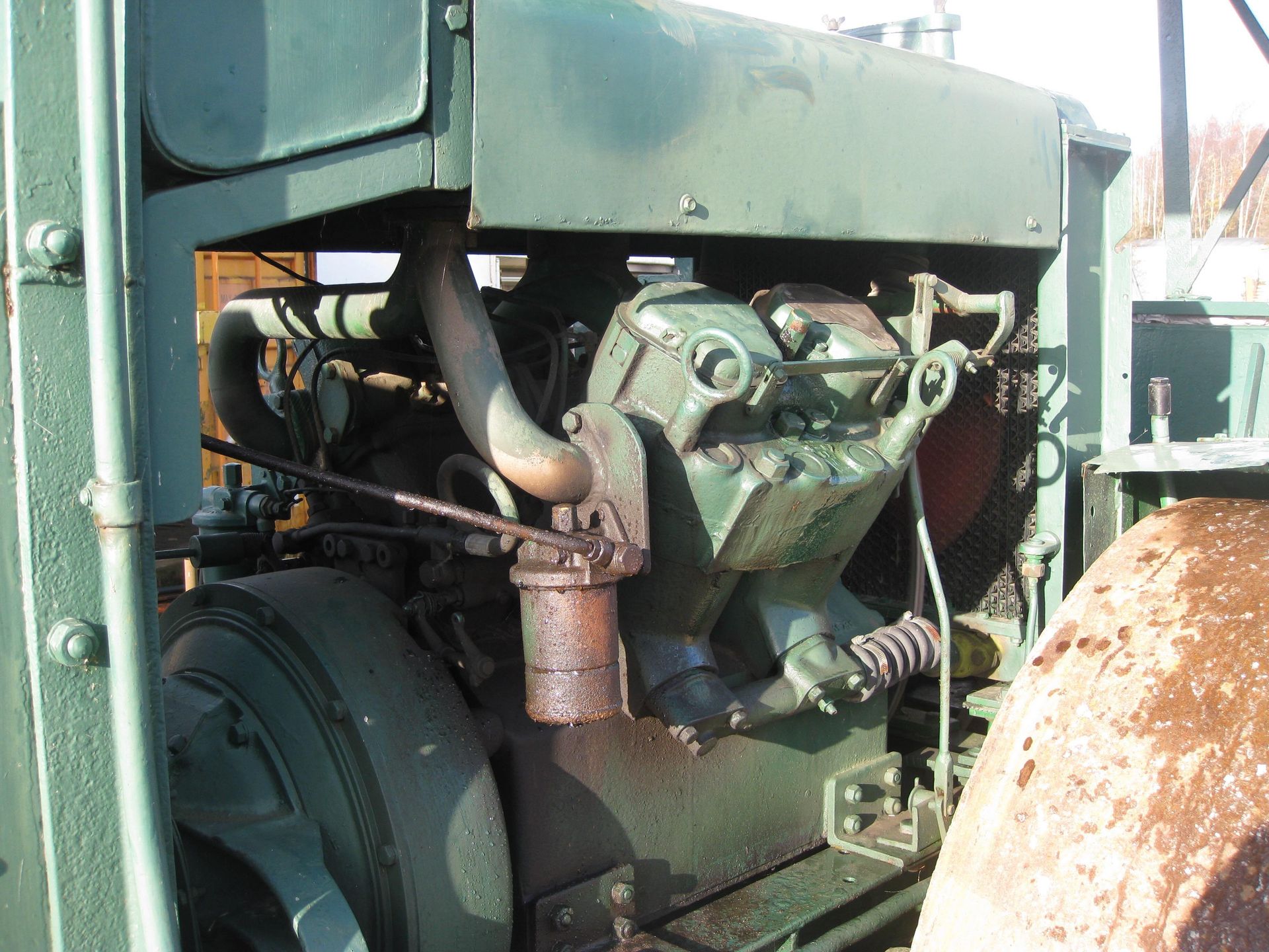
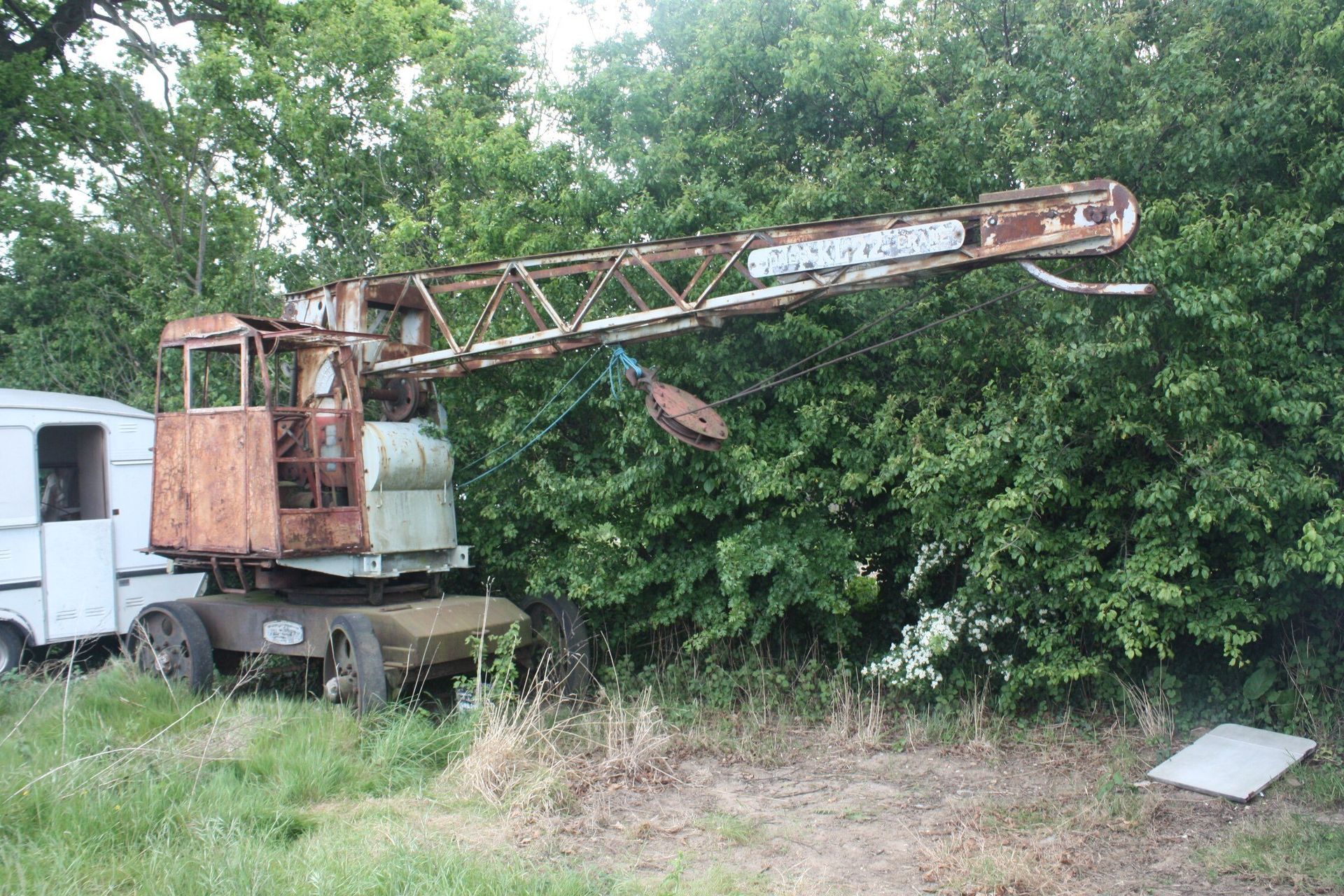
A Jones crane in a scrapyard down south somewhere
Close up on mechanicals of above crane.

Jones KL22 with a 24 foot jib and single chain discharge grab.

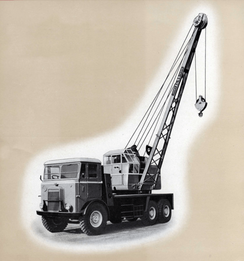
Jones KL44 mounted on a war surplus Leyland Hippo, giving a free on wheels capacity of 4 tons at 8 feet radius.
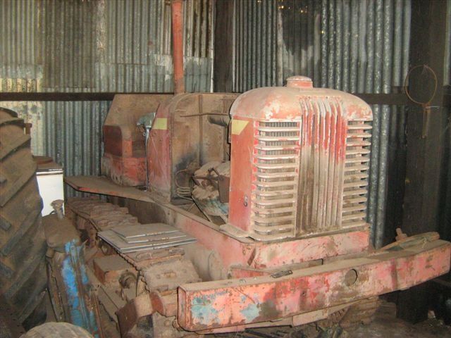
On the agricultural theme, the V95-four cylinder engine was offered as an option on the crawler tractors produced post WW2 by the bren gun carrier builder F H Loyd. The first machines used the same tracks and steering as the carrier but a later improved machine was called the Loyd Dragon.
This is a link to a Youtube video of a 2V95 in a canal boat.
These three pictures are of 2V95 engines owned by a collector in Sussex.
The first is one which had spent many years inverted in a ditch with a lot of re-manufactured parts.
More recently (June 2017) the above engine has appeared on eBay for sale with a hydraulic motor attached (and still missing the rocker covers!).

The second is of a 2V95 driving a 1902 saw bench.
This last is of a hydraulically powered 'tractor' vehicle.

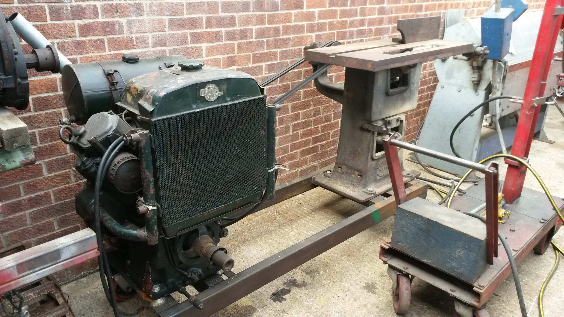
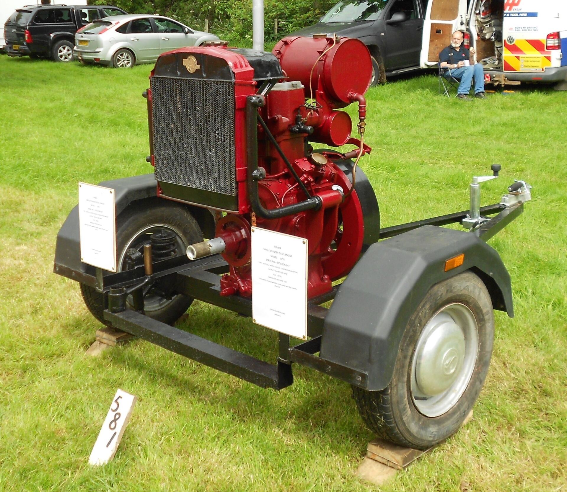
1V95 engine at Glamis 2015
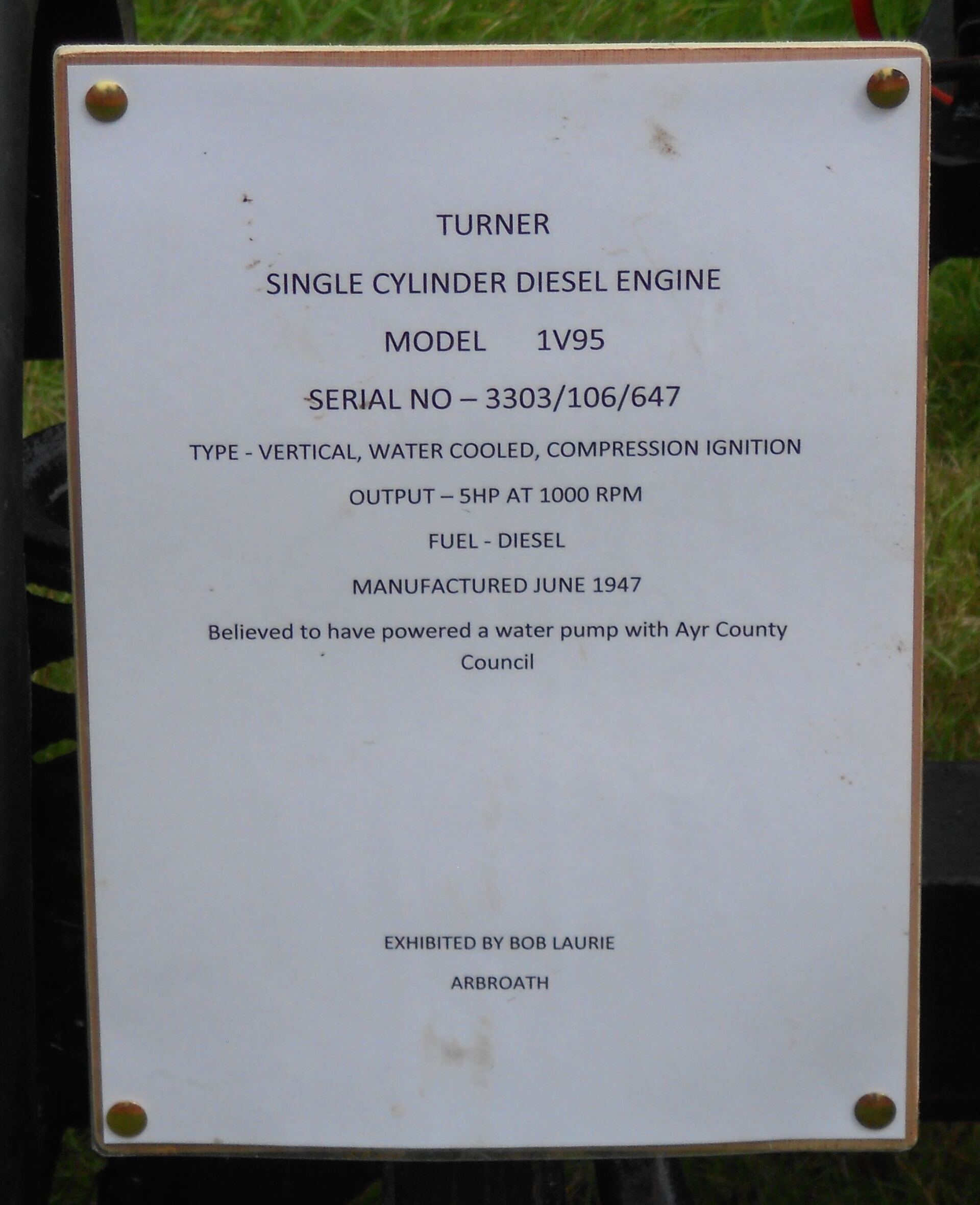
Board detailing above engine
2V95 driving a modern generator at Dorset Steam Fair

A 1V95 generator
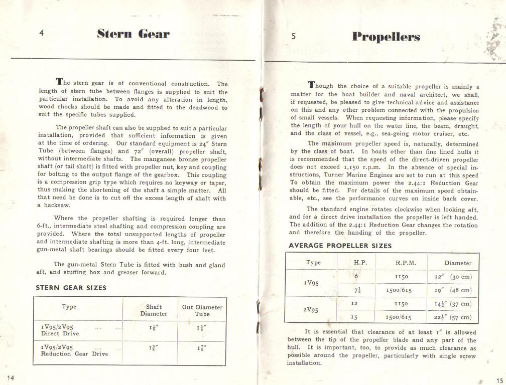
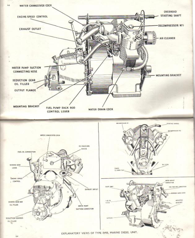
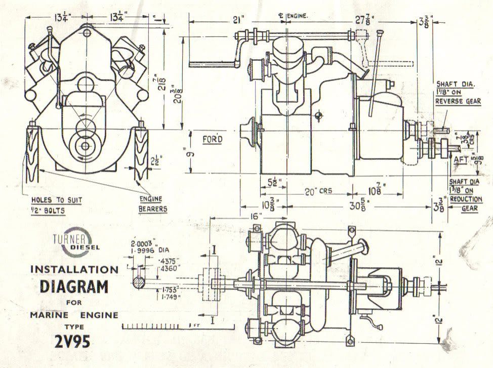
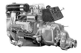
MARINE VERSIONS OF TURNER ENGINES
Turner made marine versions of the L40 and L60 and also supplied the 1V95 and 2V95 engines with gearboxes/ reduction gearing for fitting in boats.
This first picture below is a stylised image of a 1V95 released by Turner fitted with what I believe is a Meadows gearbox and then a further reduction gearbox.
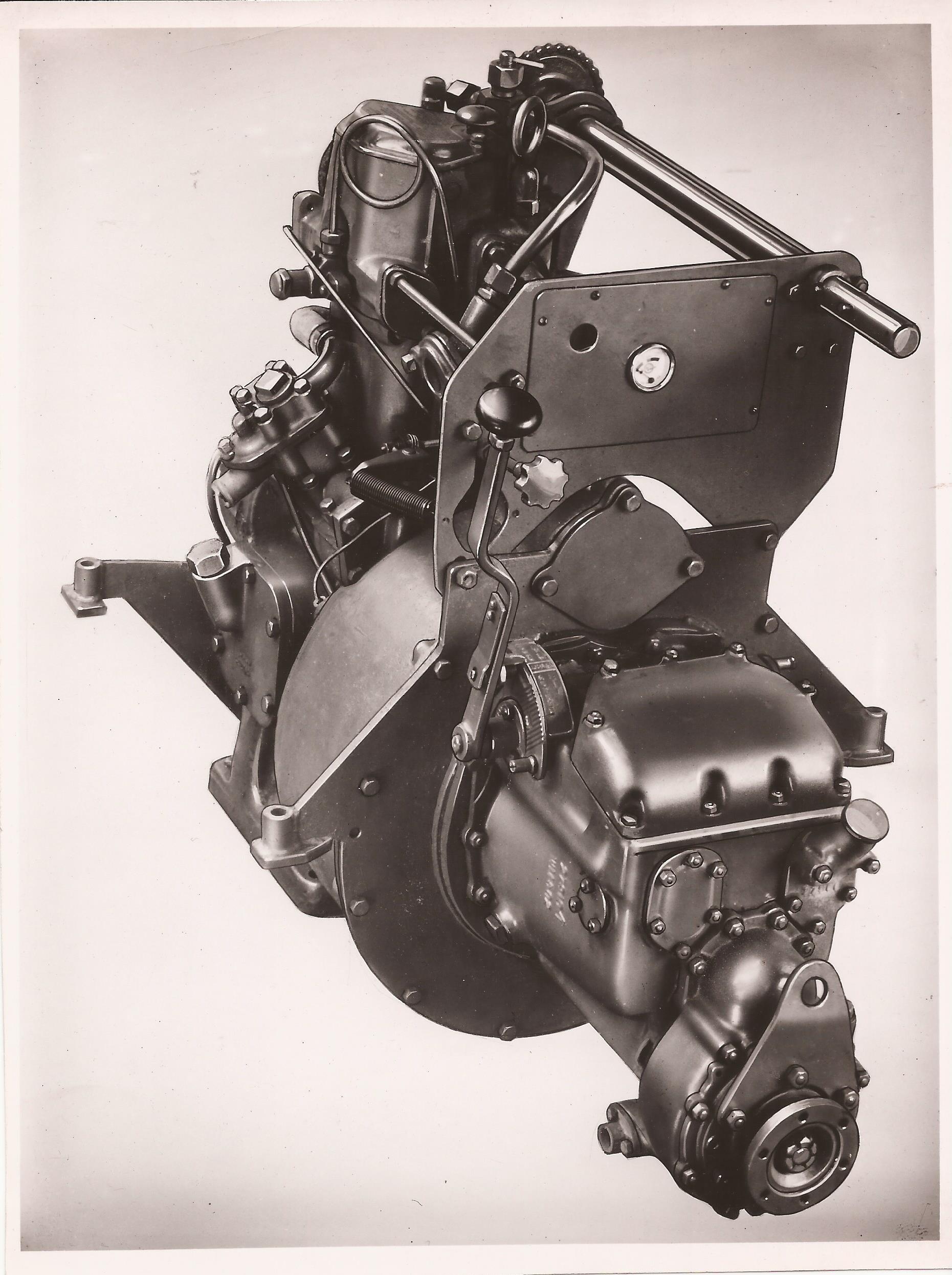
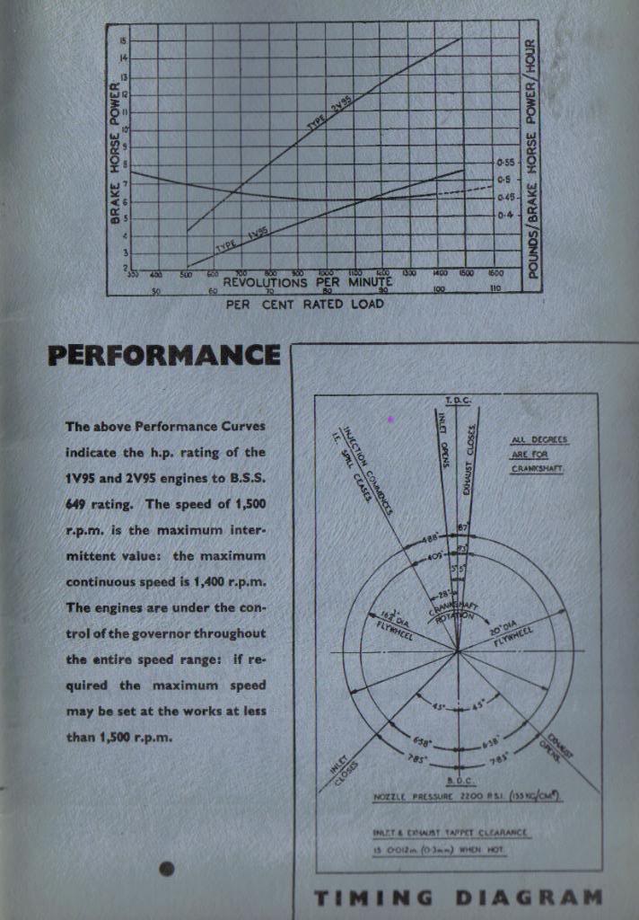
The following images are taken from the September 1958 'Engines for Small Craft' publication.
The following are four pictures of an actual 1V95 with a gearbox I acquired but have now sold on to somebody.

This engine has no head and I have no idea as to the condition of the engine or gearbox internals. This engine has now moved on to a new owner, I'll report on it in due course (January 2018).
The next series of pictures I found somewhere on the inter web.


The following two, very poor images, are of the marine versions of the L40 and L60.
The first the L40 Sea Princess.
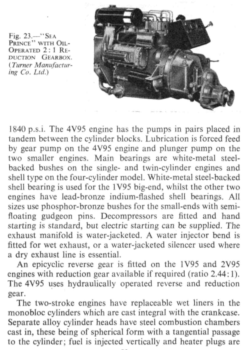
The second the L60 Sea Prince.
I hope to be able to post better pictures at some point in the future, the picture below is an improved image of an actual Sea Prince which I believe exists somewhere out in New Zealand.
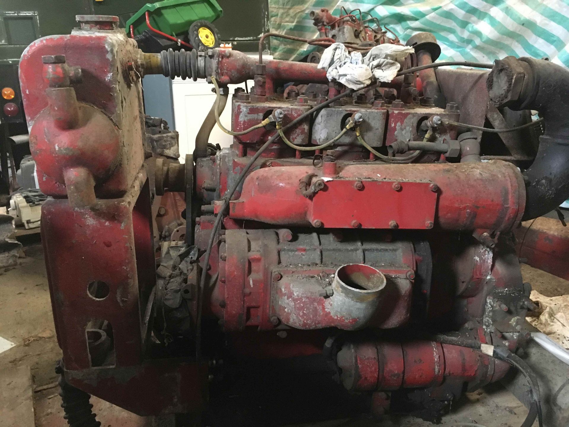
Very recently, well yesterday actually (13th July 2018), I finally properly broke open the two crates containing L60 'marinised' engines I was fortunate enough to purchase a number of years ago to have a look at them. This was prompted by a query I'd had concerning a 'hopper' unit the previous weekend at Glamis.
This first picture is of the hopper unit. If you look carefully at a picture below showing the installation of an engine in a cruiser you can see such a unit installed there.
Inspection of one of the two crated engines showed where the hopper had come from so, for the purposes of taking photo's we bolted the hopper on to the engine. Clearly there are a couple of pipes missing from and to the water cooled exhaust manifold (I'll need to look around to see if they are lying around somewhere).
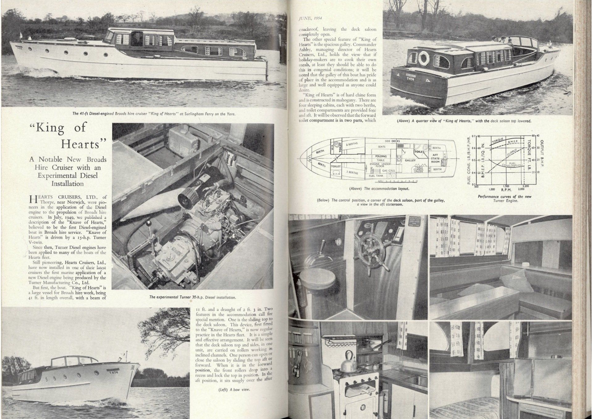
I've very recently come across a site - Broads Hire Cruisers in which one Vaughan Ashby recounts details of vessels built by Hearts Cruisers at Thorpe. It details a boat, Knave of Hearts, being fitted with a Turner L40 in 1949. These boats were used for hire on the Norfolk Broads I believe.
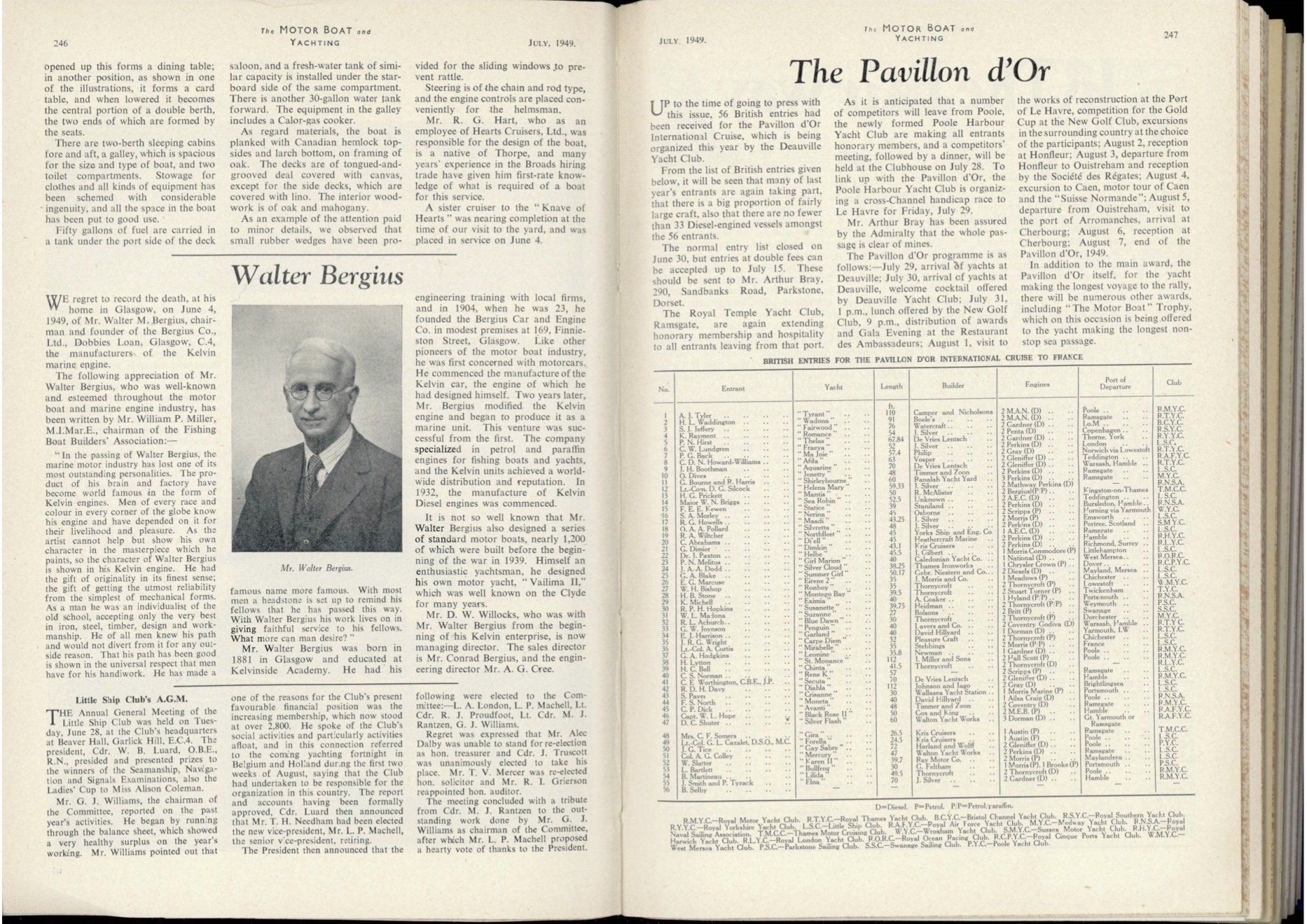
And so to diesel engines. My father installed the first one, in the “Knave of Hearts” in 1949. He commanded motor torpedo boats in the war and always respected the German E-boats because they had diesel engines, so they didn’t blow up at the slightest provocation. Maybe this was why he was the first to do it on the Broads? Everyone else, of course, said they “would never catch on”.
The first engine was a Turner diesel, a V twin with 2 separate injector pumps and was originally designed to power fire main pumps on ships. So the vibration, at low revs, was quite something. To say nothing of the noise!
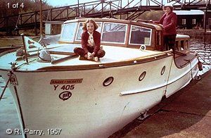
I'd like to acknowledge the Motor Boat and Yachting magazine for the following articles detailing two of the boats manufactured by Hearts Cruisers.


Dutch Turner engine advert

TURNER GENERATORS
Turner Manufacturing produced a range of generators based on the 1V95, 2V95 and 4V95 engines.
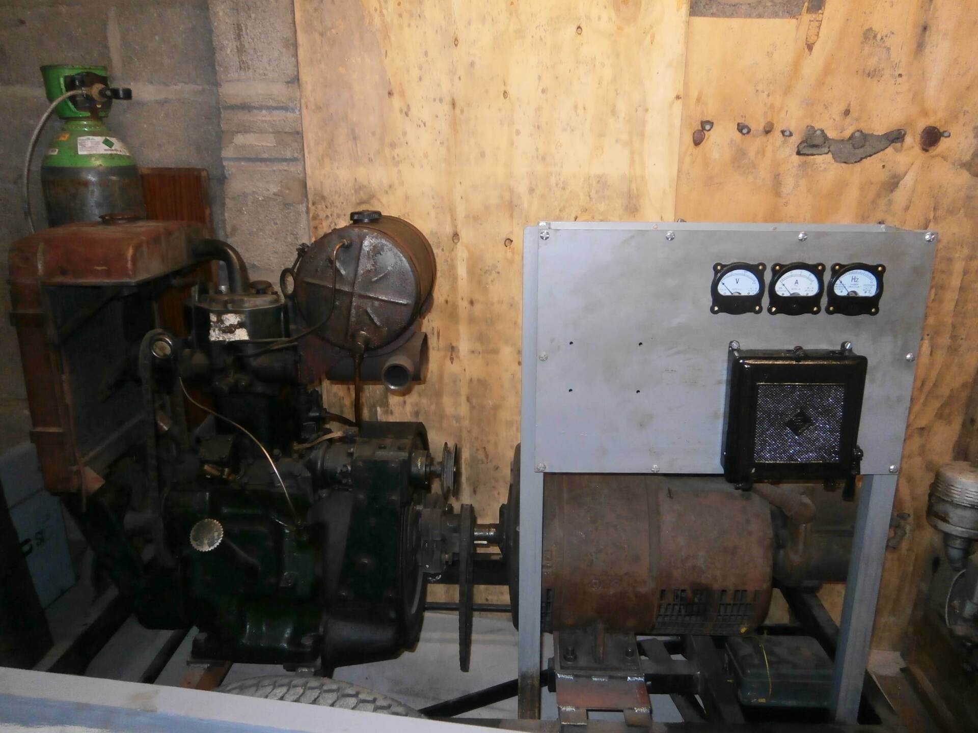
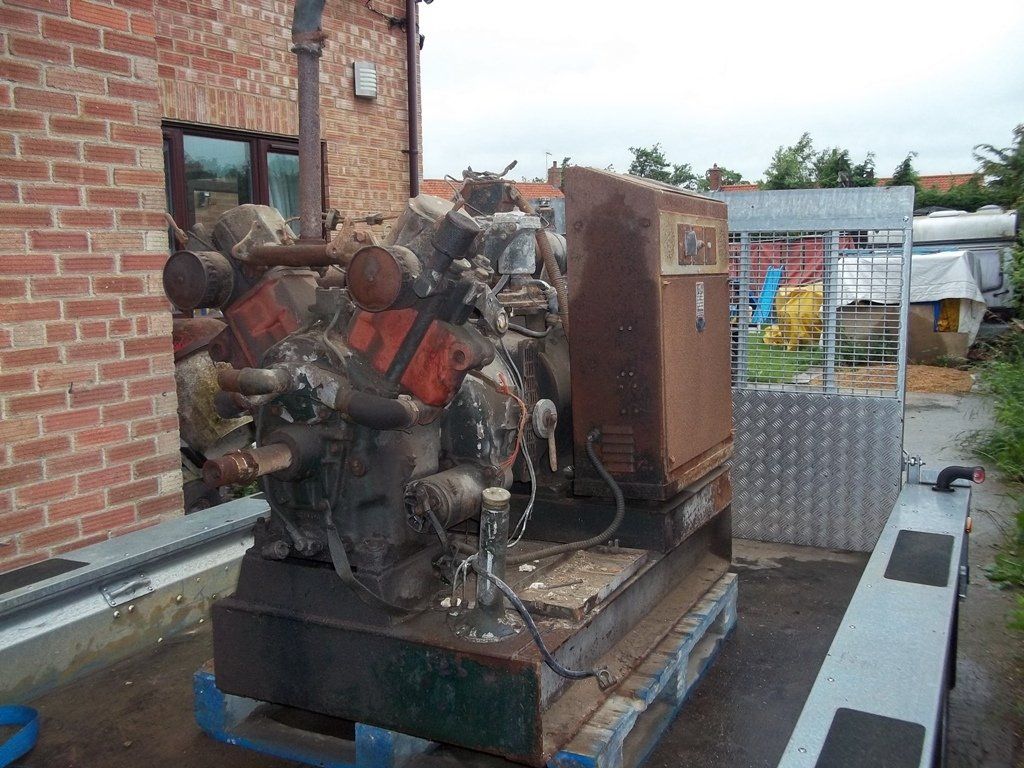
To date I am aware of an example of one I own which is a 1V95 as shown below (this, unfortunately, destroyed in the steading fire).

This generator plant is actually connected up and able to run our house and is routinely tested on line. The following photo shows the generator as installed.

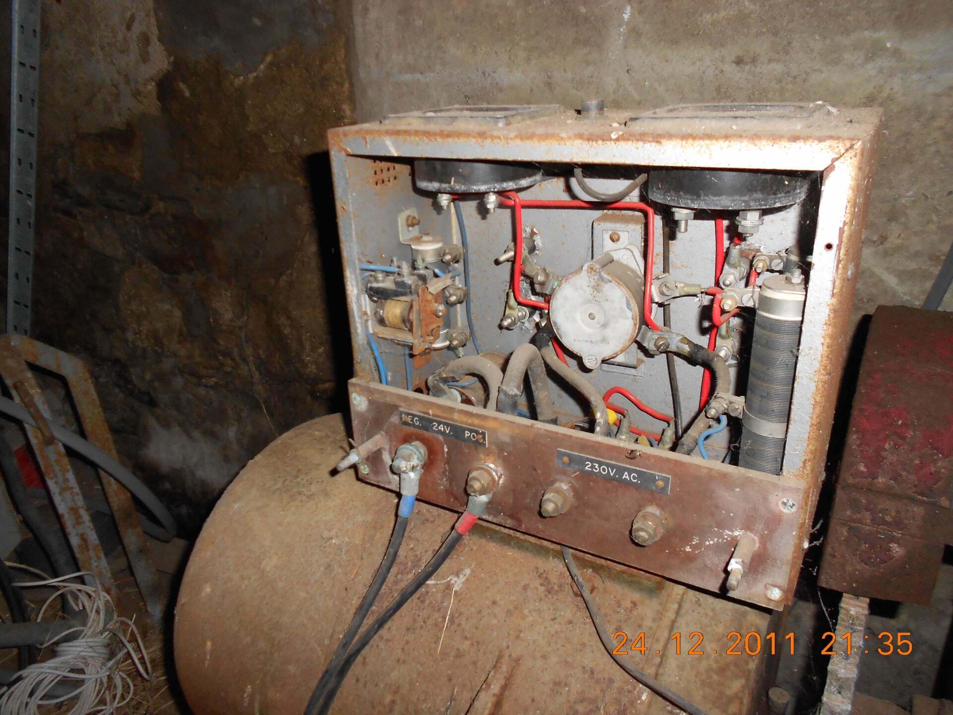
In the background is a 1V95 powered battery charger set-up. The following photo is a close up of the 'control' box.
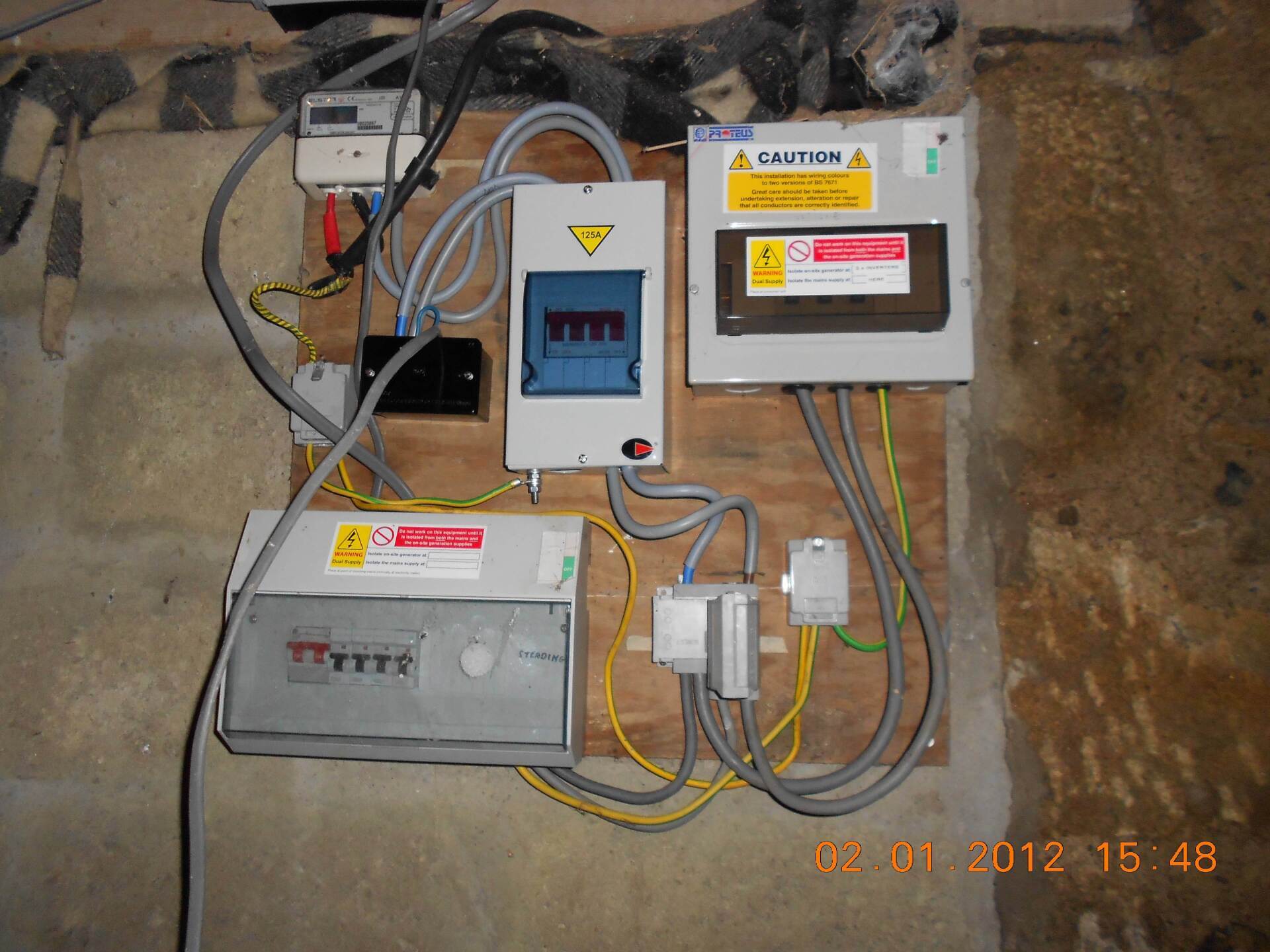
This last photo shows the generator connected (as a trial) to the incoming consumer unit via a 'pukka' change over switch. This installation has been tidied up since they photo was taken.
Very recently i.e. when setting up this page I became aware that two video's of a 2V95 generating plant had been posted in the last year. I have made contact with the owner of this plant and, with his kind permission the following pictures are posted.


The engine has suffered from frost damage but does run. If you follow the link button below it takes you to one Youtube video but there is another one available as well with the generator running at a show in Essex.
The owner advises that the engine is a prototype and that a year elapsed from the former owner ordering the device and it being delivered. It used to power a mansion house, 6 cottages and a barn apparently and clearly worked for a living.
Official pictures of Turner generators available from company literature indicate that the form of my 1V95 generator set above is the form that the 2V and 4V95 set followed i.e. there is no external exciter/ voltage regulator. The owner advises that this is a 10kVA device which is a logical progression from a 1V95 being 5kVA.
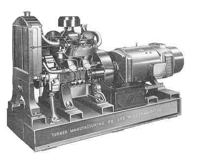
I was quite surprised to see all the complication attached to this generator set as Turner promotional literature simply shows both 2V95 and 4V95 sets as simply engines and the generator with nothing else (as in the picture above). It would be good to see a genuine 4V95 set.
It is very different from my 5kVA in that it has the exciter mounted on top of the generator and the unit on the end is an Isenthal M.S. Automatic Voltage Regulator. I have found documentation relating to this (click on the button below):-
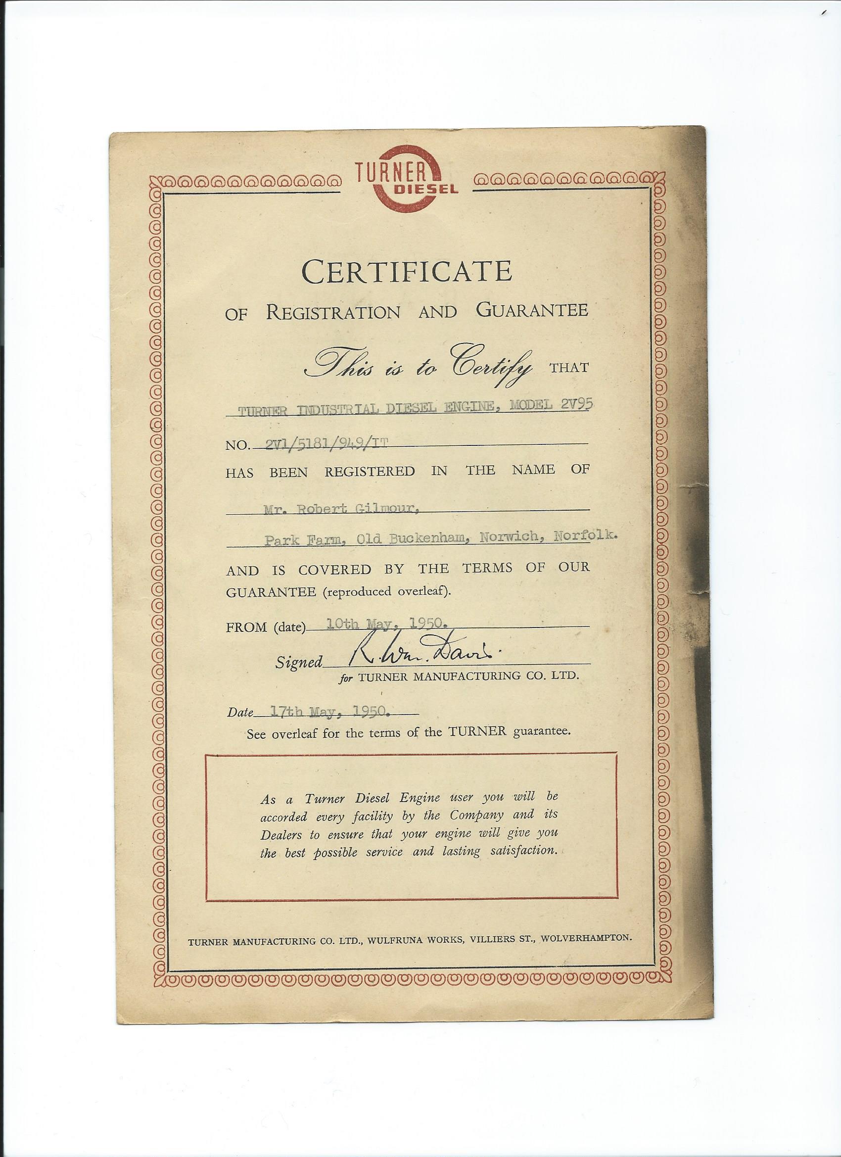
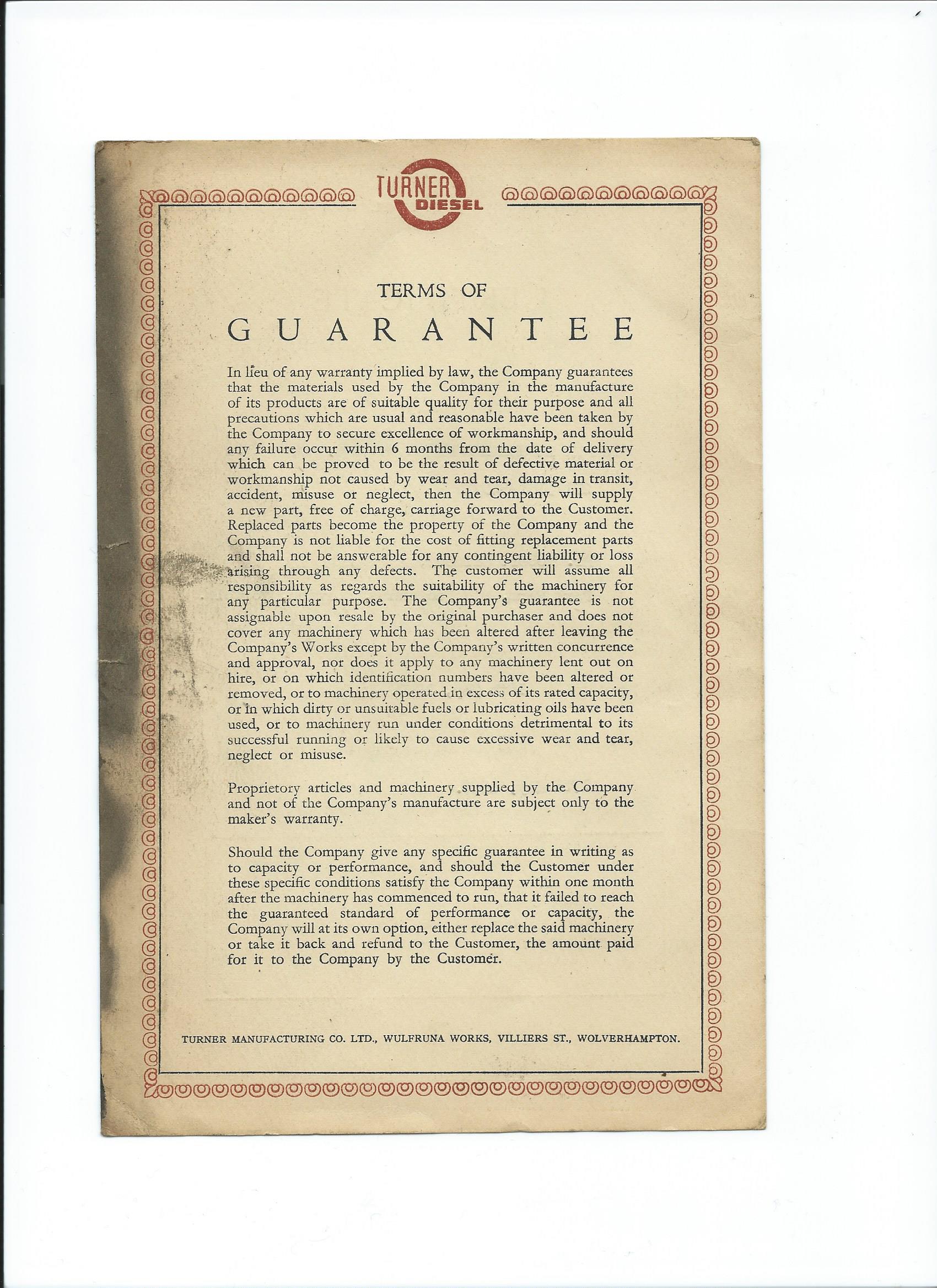
The following warranty came with the engine originally:-
I'm away from home currently but I have a document from the suppliers of the generator for my 1V95 set which I will scan and post here in due course. Once the owner of this generating set supplies me with some information relating to the generating part of his set I will see if I can find any relevant documentation as well.
The following link takes you to a copy of the installation manual for my set - Manual
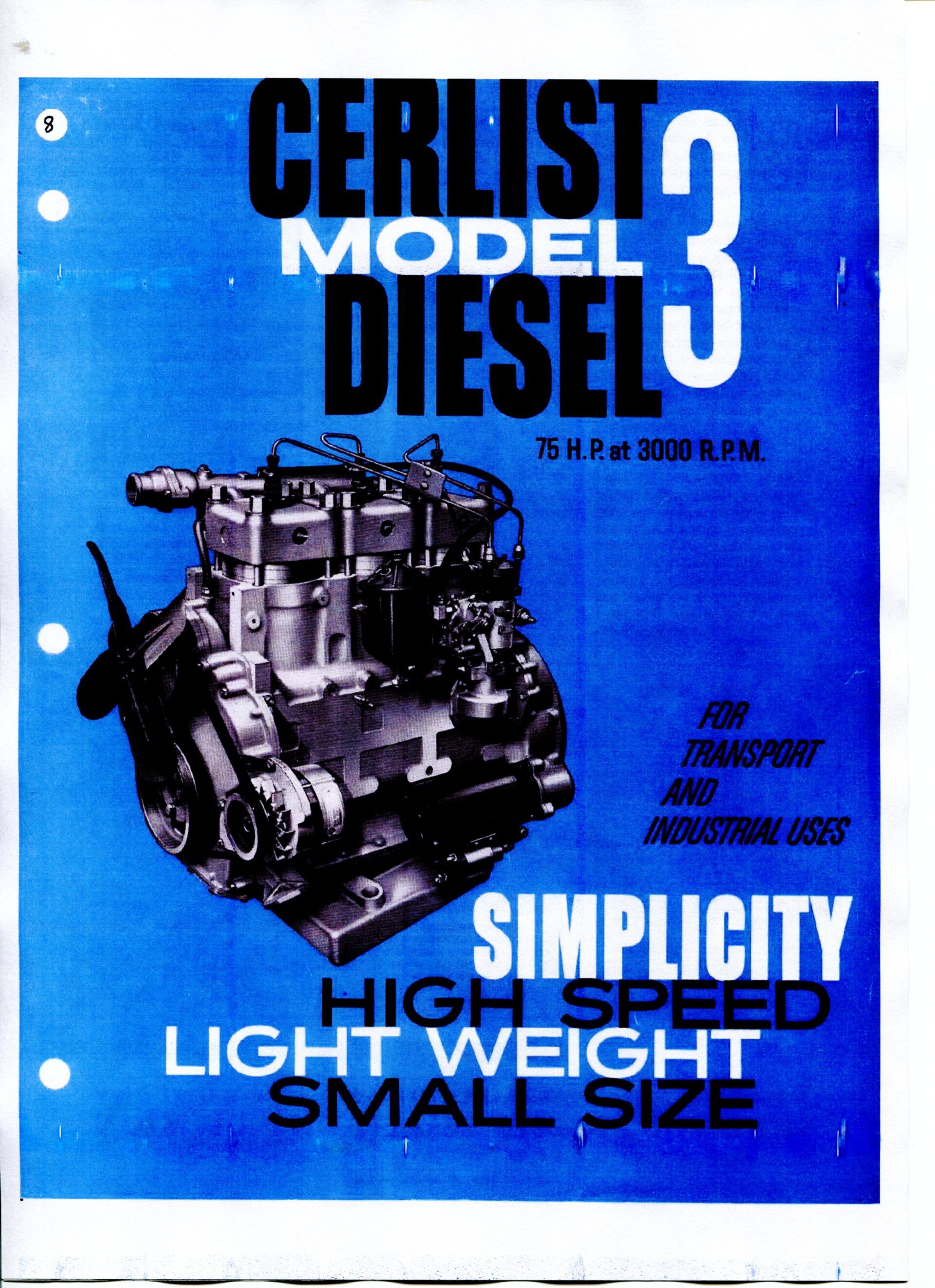
Cerlist Diesels
Whilst doing some surfing on the interweb to see what was about on the subject of Prof. List I came across the site below detailing Hans List involvement in developing an engine for use in an American Forward Control Jeep in early 1956.
The button below takes you to a site detailing this. This same site suggests that at the same time that Turner were doing a deal with AVL in Austria so too were Ford of Germany and Alfa Romeo. Time for some more surfing.
View of a 3 cylinder Cerlist engine in an FC Jeep
Cerlist Jeep Engine
CERLIST INFORMATION FROM WEHS
I would like to acknowledge the Waukesha Engine Historical Society for this section of the web site.
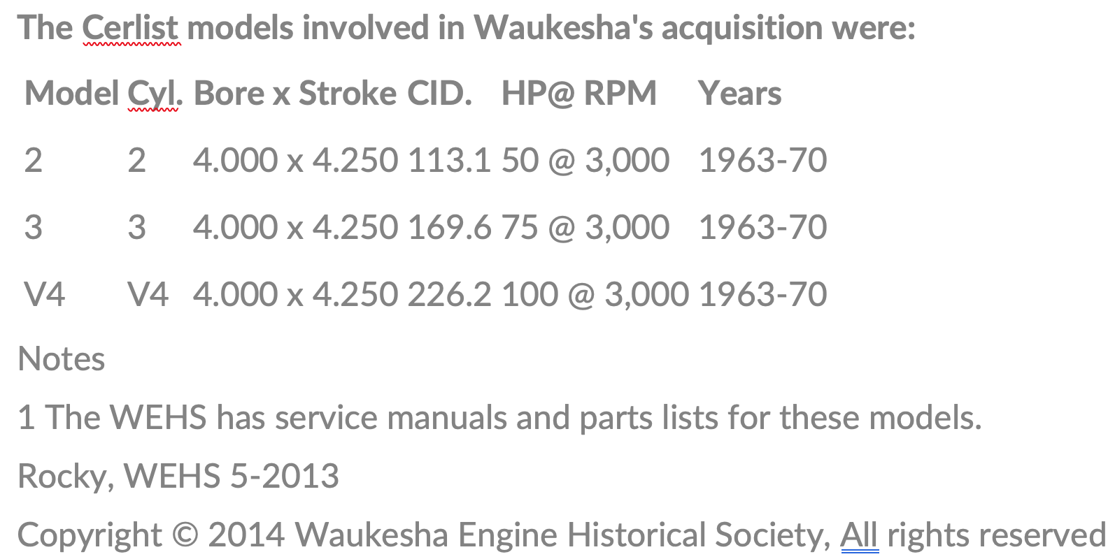
In 1963, Waukesha acquired the rights to build the unique Cerlist Diesels.
The Cerlist Diesel Co. was incorporated in North Carolina in 1956 by Peter Cerf. The name of the engine company was derived from the names of Cerf and Dr. Hans List of Austria, who designed the engine.
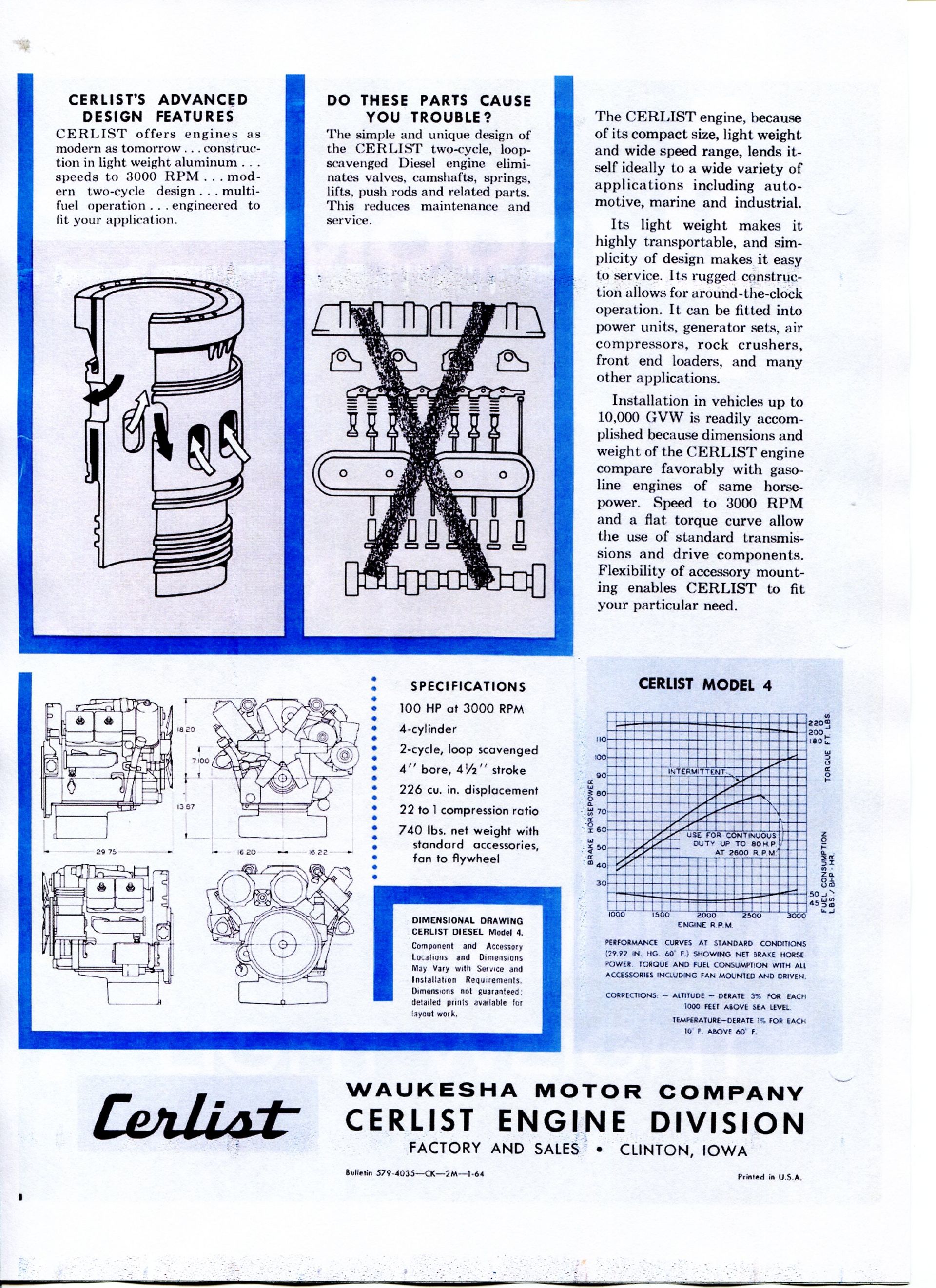
The 2-cycle, high-speed, aluminum, supercharged diesels were unique in that they had no valves, and were "loop-scavenged". Multiple intake and exhaust ports were cast through the cylinder wall near the bottom of the piston stroke. The intake ports were angled upward so that the incoming rush of supercharged air was directed up and over the top of the cylinder and then back down in a looping fashion to the exhaust ports, carrying exhaust gases with it and filling the cylinder with a fresh charge of air.
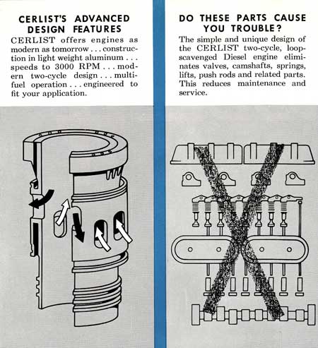
Cerlist Diesels were originally manufactured in the Cerlist Diesel plant in Burlington, NC until the company went bankrupt. Peter Cerf had estimated that several thousand were manufactured. Although the engines were used primarily in military applications, they were used in some industrial and marine applications as well.
During the Vietnam War, the Air Logistics Corp, of Monrovia, CA used the 3-cylinder Cerlist Diesel to drive the jet fuel pump of their Boondocks Air-Transportation Fueling System. The system was a portable unit that included the engine driven pump, two huge flexible fuel bladders along with all the piping and valves that could be towed to the airfields built out in the boondocks.
The Waukesha Cerlist Division was located in Waukesha's Clinton, Iowa plant under the direction of Peter Cerf, Sales Manager. Cerlist Diesels were discontinued in 1970. All the WEHS knows for sure about the fate of the Cerlist's Diesel is that in 1980, the entire inventory of Cerlist Diesel parts were sold to Engine & Equipment Co., Salt Lake, Utah.
CERLIST SALES BULLETINS
The following sales bulletins were supplied by WEHS.


Another Cerlist Jeep engine

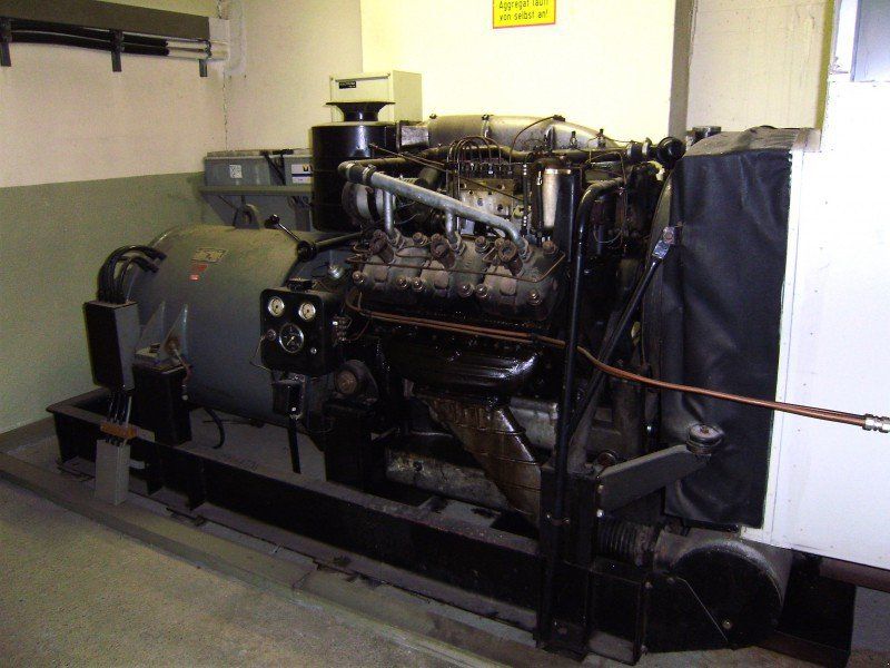
Gräf & Stift
I don't have a lot of information on this firm as yet but the engines were developed in conjunction with Professor Hans List.
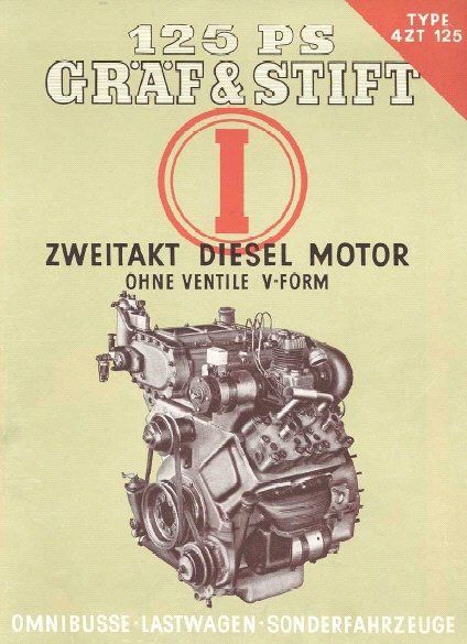
The following (poor) photo is, I believe of a V4:-
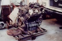
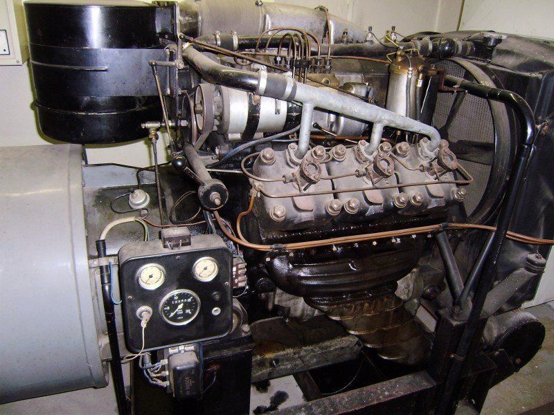
The two following photo's show, again I believe, a V6 version of the engine:-
I will endeavour to add more information when I find it, anybody reading this who has any information is welcome to contact me.
January 16th 2019 - courtesy of two continental sites (graefford and fk) there is the following information:-
Much later, Gräf & Stift and Ford come together again: In the 1950s, Gräf & Stift is building a unique diesel V4 and V6 engine with the 2-stroke compressor principle. These engines were designed by AVL / Prof. List designed in Graz and developed for the production of Gräf & Stift coaches. Unfortunately, they proved to be quite unreliable in the Ford FK truck, thus contributing to the demise of truck production at Ford in Cologne.
and
The new 1955 Ford at the Frankfurt Motor Show presented a modern, distinctive lines. The striking face with the chrome "shark teeth" and the characteristic sound of the newly developed, valveless two-stroke diesel engines. These AD4 or AD6 engines with up to 120 hp were the ones that finally broke the backlog of the German Ford truck. In an effort to achieve an increase in performance without altering dimensions and weights, Ford decided on the two-stroke diesel with reverse purge, vortex chambers and indirect injection developed by the Graz Professor and two-stroke supporter Hans List (AVL). These engines were designed in 90 ° V shape and therefore took up little space, space, which benefited a short cab and thus a longer cargo area. Ford had high expectations for the engine because, theoretically, it had advantages over other diesel engines, such as low fuel consumption, the use of light metals to save weight and a cost-effective modular system for all three engine variants on offer. In practice, however, the engine of Professor List, who had previously developed the Krupp two-stroke diesel, was not mature. As a result of insufficient testing, a variety of defects arose (piston, lubrication, etc.).
I found information on a German language site that suggests that Gräf & Stift were impressed with the torque and fuel economy of the List design and invested heavily in machinery to manufacture it at relatively low cost. I believe the engine proved to not be very durable and warranty claims cost the company a lot of money.
I believe this is the 6 cylinder version although I have no idea what vehicle it was installed in:-

Most recently (July 2020) I have been provided with the below video of an identical engine to the one above (Ford AD6?) engine running.
I believe the engine was fitted to a OLZT-4 type bus? The picture below is a very poor one but the only one I could find of this vehicle:-
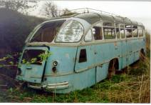
PALTEN PAA VAN
I found this article in the 26th February 1954 edition of the Commercial Motor:-
New Two-stroke Air-cooled Oiler
PAA 1-TON van similar in appearance, layout and dimensions to the German Volkswagen, but with a two cylindered two-stroke air-cooled oil engine at the rear, is now being built in Austria. A prototype of this new Palten van, made at Rottenmanh Styria, was displayed at the Vienna Show, which coincided with the Geneva Salon.
The van is made almost entirely of aluminium alloy, apart from the pressed-steel underframe supporting the floor and body and as a complete vehicle weighs under 151 cwt. The 991cc oil engine, with the two cylinders at 90°, was designed by Prof. List, of Graz University, and is being built by Warchalowski of Vienna (a tractor manufacturer).
Many details of the engine are similar to those of the Turner unit, which was also designed by Prof. List. It operates on the loop-scavenge principle and has direct injection, an output of 20BHP being derived at 3,000RPM.
The engine, differential and gearbox. using light-alloy castings and bolted at the clutch bell-housing to form a unit, weighs 2cwt. It is claimed that the van has a maximum speed of 50MPH and a fuel-consumption rate of 53 m-P.g
It’s wheelbase and body dimensions are similar to those of the Volkswagen and the Palten van has independent suspension of all four wheels and full forward control. A four-speed synchromesh gearbox is employed.
Since I first put this site together I have, at odd times, added bits too it as I've become aware of them. Whilst re-composing this version of the webs site at the back end of 2022 I Google Palten PAA Van and see that a model making firm have produced a model of this vehicle and produced the information listed below (with acknowledgement to 'house of modellers':-
The story of one of the worlds most successful transport vehicle began with the start of the production of the Type 2 at the Volkswagen factory in Wolfsburg on March 8th, 1950. The delivery van was very popular, not only in Germany, also in Austria. This gave government agencies, the institute AVL List and the Palten-Stahlindustrie GmbH the idea of offering an own, similar small van.
The company Palten-Stahlindustrie GmbH, located in Rottenmann (Styria) had absolutely no experience in the field of automotive construction and production. As a support, the back-then latest VW T2 was bought and examined very carefully. But the thorough check of the van did not led to own knowledge, which in turn would have implied an own development. Rather the VW T2 was more or less copied. The result was a van that shared many common characteristics with the Volkswagen van. The only area, which got a personal note by the Austrians, was the front area. In contrast to the German model the Austrian van had an utterly even front, without the big, striking V-shaped ribbing. Only the two flush-mounted, high-positioned front lights and the embossed lettering “Palten-Diesel” were in contrast to the rest of the front end. Also differing from the VW example the semicircular windscreen had no division bar, but was built as one part. Production of some experimental vehicles took place at the German body maker Westfalia. Besides the transporter version it was also planned to offer a pick-up and a bus version. All three versions should share the same chassis and a 2-cylinder V-diesel-engine with 1.020 cc and 20 hp.
In 1954 in total 5 copies were set on wheels. They were used at several exhibitions to attract customers. In the end an agreement with the Spanish company FADISA was made and 2.000 copies were produced for the Iberian market in 1956.
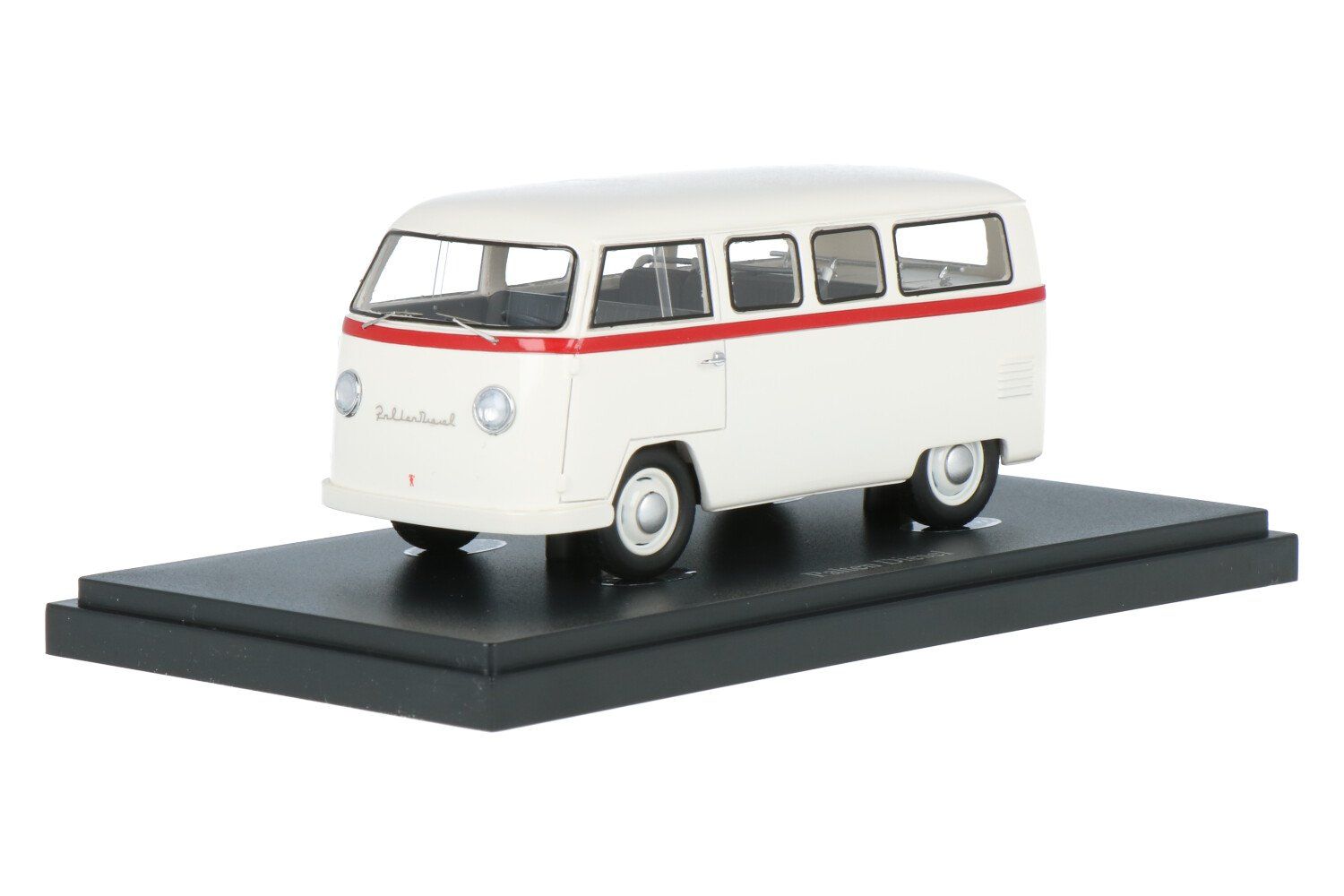
I have no idea if there is an actual example of this vehicle extant but there are models as shown above.
Warchalowski Tractors
I haven't been able to find out a great deal about these and am not actually entirely sure the engines fitted had anything to do with List.
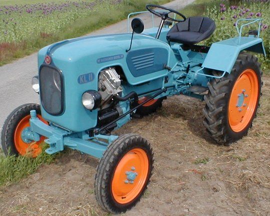
I believe the YouTube video below is of a Warchalowski 'V' twin diesel.
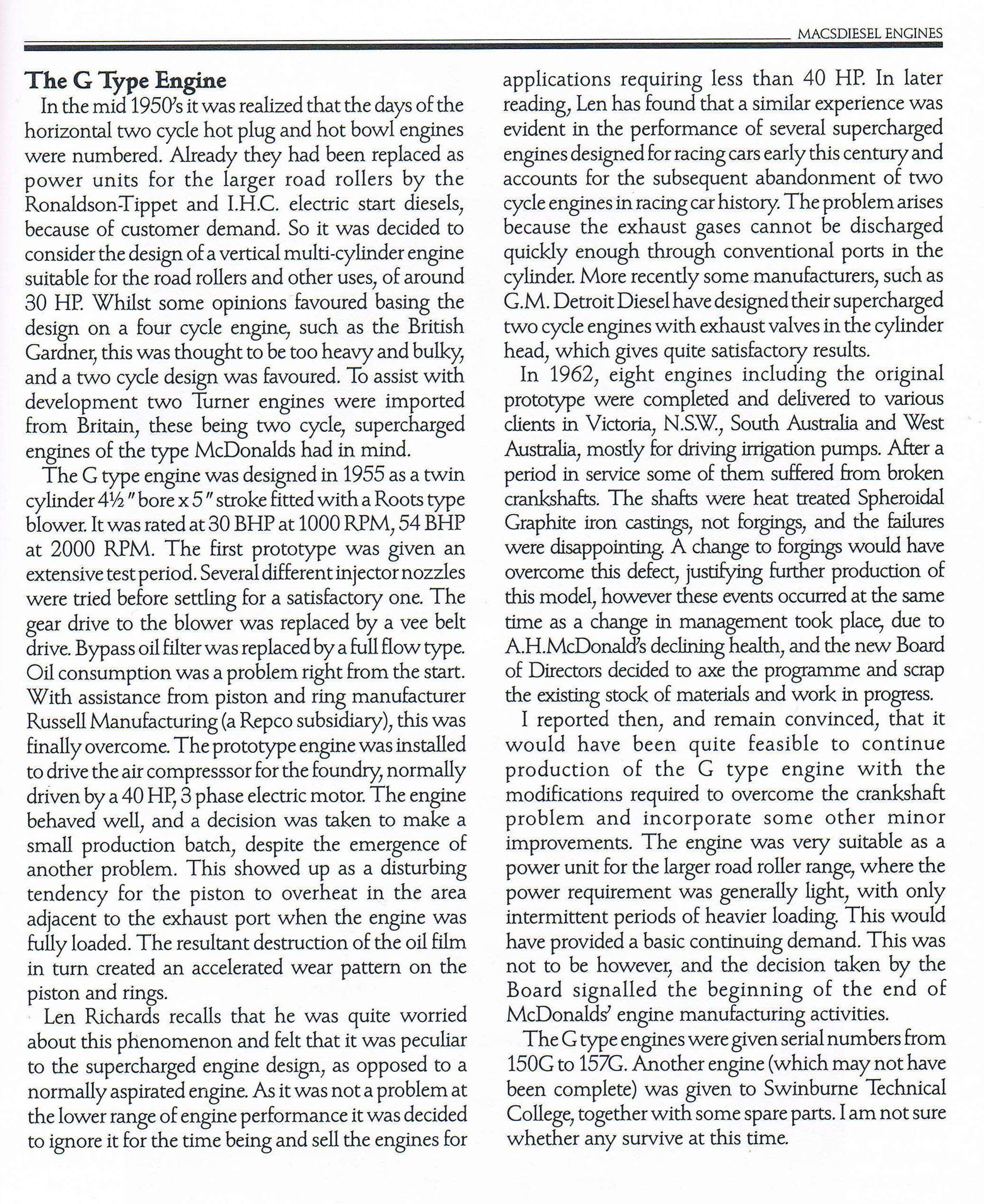
A H McDonald
The following information has been supplied by Warwick Bryce of Victoria Australia.
Another version of the engines designed by Dr List was made by A H McDonald, the pioneering Australian tractor manufacturer. They used two Turner-List engines to help them design their own version, the G Type, intended for use in small road rollers. The extract shows that a small number of engines were supplied for industrial applications only. Warwick advises that the engines from the technical college have survived in the hands of a private collector who does not want to be named.

Ford of Germany
I have read that List also was involved with engines used by Ford of Germany but I haven't been able to find much information so far.
I have found this link to a German language site
From further reading there was some kind of connection between Graf & Stift and Ford so Ford were apparently using the same List derived engines in some of their trucks:-
Much later Gräf & Stift and Ford get back together: Gräf & Stift built in the 50s a unique diesel V4 and V6 engine after the 2-stroke principle with compressor. These motors were of the AVL / Prof. List designed in Graz and developed for Gräf & Stift coaches for series production. Unfortunately, they proved in the Ford FK truck to be quite unreliable and thus contributed its part to the demise of truck production at Ford in Cologne.
These four photographs, received in June 2018, are of a German built Ford AD6 engine as used in the Cologne produced FK series of trucks. The engine is located in Denmark. It was removed by Ford from the truck to be replaced by a D6 engine but was then kept "hidden" in the workshop for many years. Eventually it was bought by the current owner who has quite a collection of engines and tractors - checkout


The button below is a link to a railway 'engine' powered by a Jenbach JW35 which is, as far as I can tell the same basic engine as the one Turner produced under licence from List.
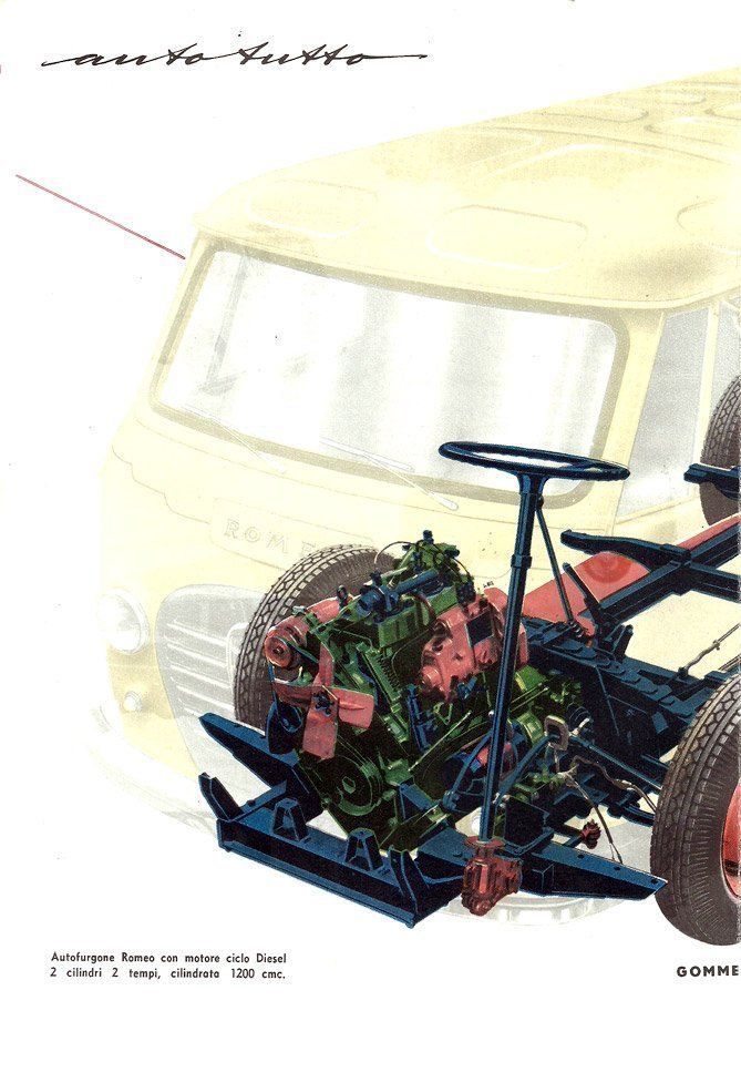
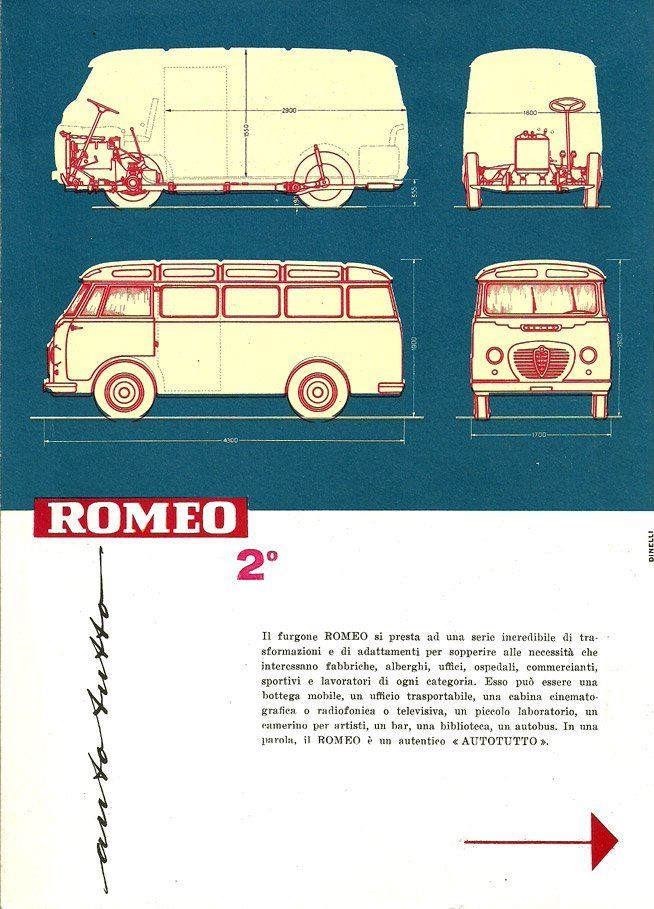
It took a little bit of finding but yes Alfa Romeo did indeed have a version of the same List engine as Turner and Jenbach as the button link below shows although it has a smaller overall capacity.
The engine above is the 1146cc Romeo List version.
I am currently try to find out a little bit more about Romeo's. Given the other users of the List designed engine used it in its original capacity of some 1400cc it seems strange Alfa apparently chose to make it an 1160cc device. The engine differs from the other two known versions of the original List design in that the supercharger is moved to the opposite side of the block and the engine only produces a claimed 30HP (against the 35HP of the 1400cc version).
At this point I am not at all familiar with the Romeo vehicle but I am trying to find more information about these units.
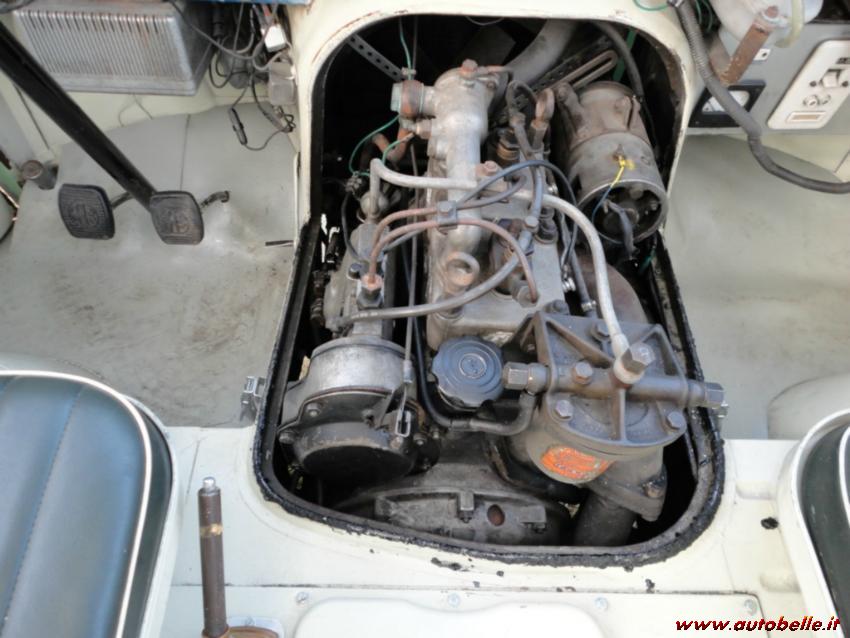
I have just purchased a manual, in Italian, relating to servicing the diesel engine. I will need to get this translated at some point but the three following images show how this derivative of the List engine looked:-

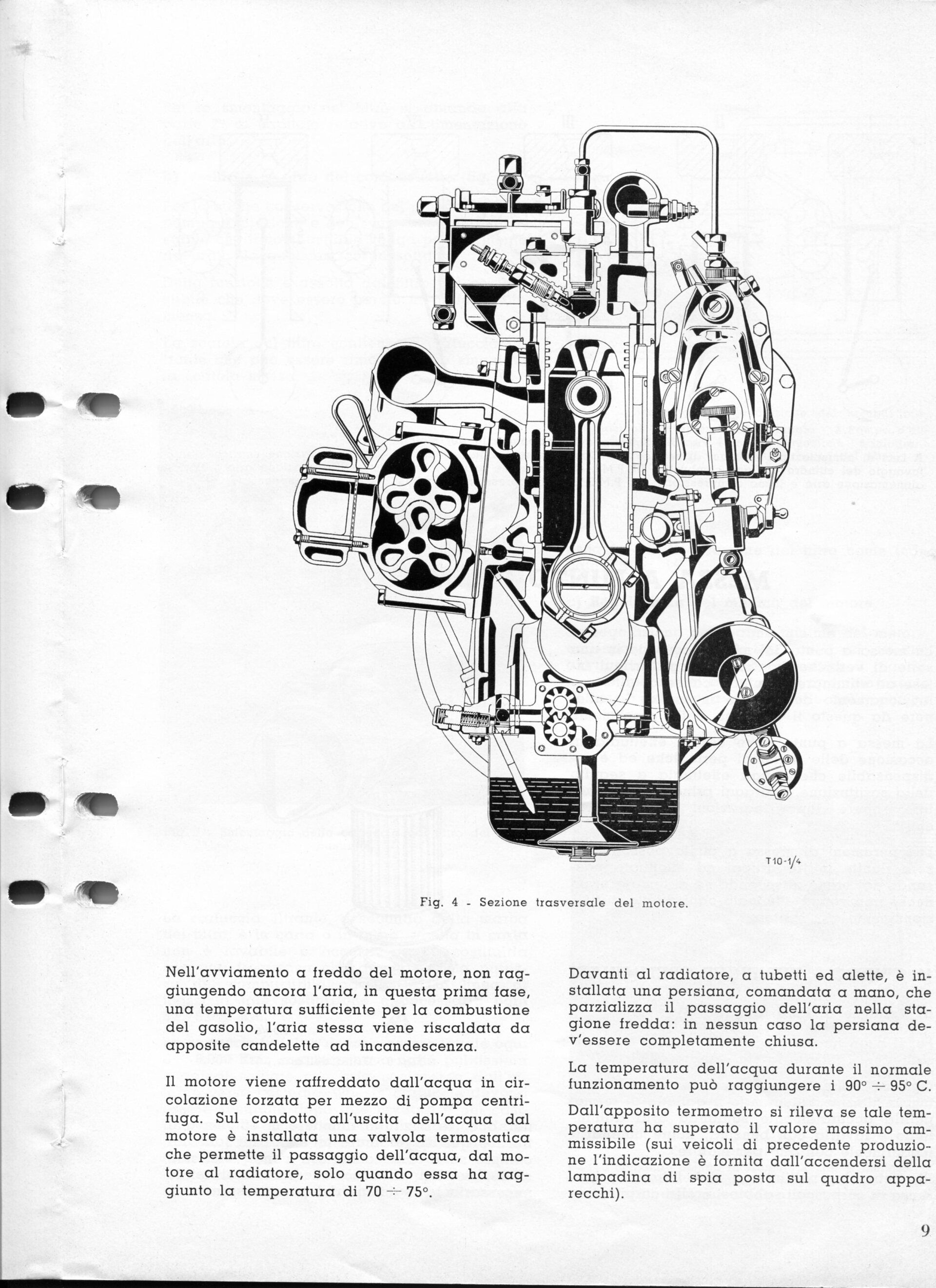
List Diesel engine powered Romeo

I believe this is a USA based vehicle and in this form even my good lady wife isn't opposed to the look. These vehicles are reported to be rare and there may only be the one known diesel engine left.
I'm trying to determine if it would be possible to get a Turner List L40 unit into the engine bay as this would be one option if I found an old originally diesel equipped vehicle.
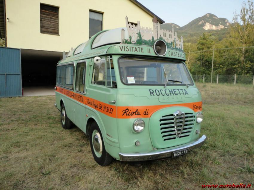
This vehicle was up for sale back in 2013 for a mere €42,000. I have no idea as to whether or not it sold, the engine bay is shown below.
Most recently I've been contacted by an Italian gentleman, Luca Montanari, who has kindly offered to translate the Italian language Romeo 'workshop' manual I won on eBay.
He has also provided a couple of links to Italian language sites which show a couple of vehicles and the engine installations.

I have had another somewhat strange link to a document featuring Turner List engine. The link below should work but be warned the document is some 8.5Mb in size.
Essentially it is a document about what must be pioneering work on using lasers to analyse diesel combustion and they had two engines they were working on. The first was a Turner and the second a TACOM. Results with the Turner enabled them to improve their testing technique on the second engine.
It is quite technical but you have to ask why, in the mid seventies, a US based research centre chose a Turner engine? I wonder if it is any part something to do with the Cerlist engine connection?
The following section is lifted from this report:-
The Turner engine experiments were not very successful. However, the need to use a crossed-axis ionizer was established, and the feasibility of extracting a gas sample from the combustion chamber of a diesel engine and of using molecular beam mass spectrometry techniques to measure species intensity, mass spectra, and translational velocity was demonstrated. The results of the Turner experiments also suggested changes that will better match the sampling nozzle orifice size, nozzle angle, source skimmer distance, and skimming technique to the ranges of pressure and temperature that occur in diesel engine combustion chambers. The beam attenuation problems discussed earlier suggested the following:-
1. Using a much larger coupling bellows diameter.
- Resizing the sampling orifice.
- Using a slender (22-deg) warm conical skimmer.
- Decreasing the separation between sampling nozzle and skimmer.
These improvements and others were used in applying mass spectrometry to the TACOM research engine.
